


Chapter 7. Usage of Various Functions
7-19
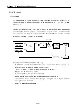
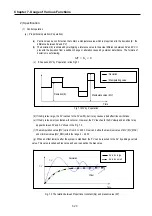
7.1.4 PID control
1) Introduction
This chapter will provide information about the built-in PID (Proportional Integral Derivative) function of GM7U main unit.
The GM7U series does not have separated PID module like GM 3and GM4 series, and the PID function is integrated
into the main unit.
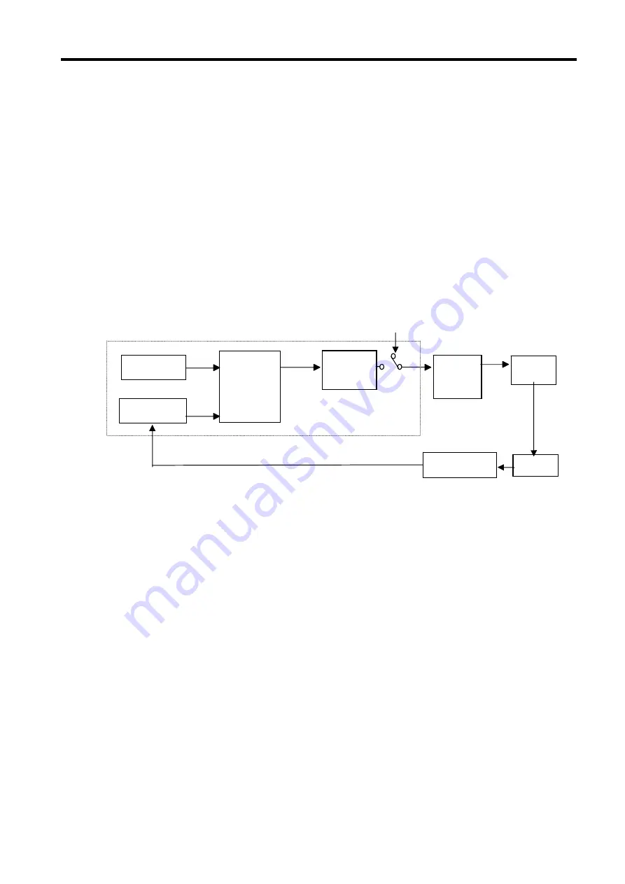
The PID control means a control action in order to keep the object at a set value (SV). It compares the SV with a sensor
measured value (PV: Present Value) and when a difference between them (E: the deviation) is detected, the controller
output the manipulate value (MV) to the actuator to eliminate the difference. The PID control consists of three control
actions that are proportional (P), integral (I), and derivative (D).
The characteristics of the PID function of GM7U is as following;
•
the PID function is integrated into the CPU module. Therefore, all PID control action can be performed with
instruction (PID7,PID7CAL) without any separated PID control module.
•
P operation, PI operation, PID operation and On/Off operation can be selected easily.
•
PWM(Pulse Width Modulation) output is available.
•
The manual output (the user-defined forced output) is available.
•
By proper parameter setting, it can keep stable operation regardless of external disturbance.
•
The operation scan time (the interval that PID controller gets a sampling data from actuator) is changeable for
optimizing to the system characteristics.
•
SV Ramp and Delta MV function are available.
P I D
calculation
Set Value
Present Value
PV
SV
MV
Manipulation
value
Manual MV
D/A
converting
module
Control
object
Sensor
A/D
converting
module
Automated MV
Summary of Contents for GLOFA G7M-DR20U
Page 28: ...Chapter 4 Names of Parts 4 3 2 G7M DRT60U N 3 G7M DT60U N 4 G7M DT60U P...
Page 29: ...Chapter 4 Names of Parts 4 4 5 G7M DR60U DC 6 G7M DRT60U N DC 7 G7M DT60U N DC...
Page 31: ...Chapter 4 Names of Parts 4 6 3 G7M DT40U N 4 G7M DT40U P 5 G7M DR40U DC...
Page 32: ...Chapter 4 Names of Parts 4 7 6 G7M DRT40U N DC 7 G7M DT40U N DC 8 G7M DT40U P DC...
Page 33: ...Chapter 4 Names of Parts 4 8 4 1 3 30 point main unit 1 G7M DR30U 2 G7M DRT30U N 3 G7M DT30U N...
Page 34: ...Chapter 4 Names of Parts 4 9 4 G7M DT30U P 5 G7M DR30U DC 6 G7M DRT30U N DC...
Page 36: ...Chapter 4 Names of Parts 4 11 2 G7M DRT20U N 3 G7M DT20U N 4 G7M DT20U P...
Page 37: ...Chapter 4 Names of Parts 4 12 5 G7M DR20U DC 6 G7M DRT20U N DC 7 G7M DT20U N DC...
Page 38: ...Chapter 4 Names of Parts 4 13 8 G7M DT20U P DC...
Page 159: ...Chapter 7 Usage of Various Functions 7 52 c Program...
Page 183: ...Chapter 7 Usage of Various Functions 7 76 c Program...
Page 253: ...Chapter 8 Communication Functions 8 27 b When uses Ch 1 Built in RS 485...
Page 356: ...Appendix 1 System Definitions App1 9 6 Position Parameter...
Page 357: ...Appendix 1 System Definitions App1 10 7 High Speed Counter Parameter...


