


Chapter 7. Usage of Various Functions
7-108
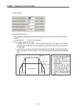
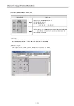
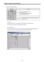
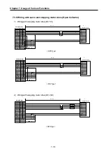
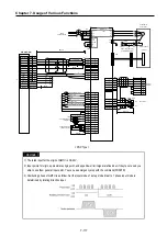
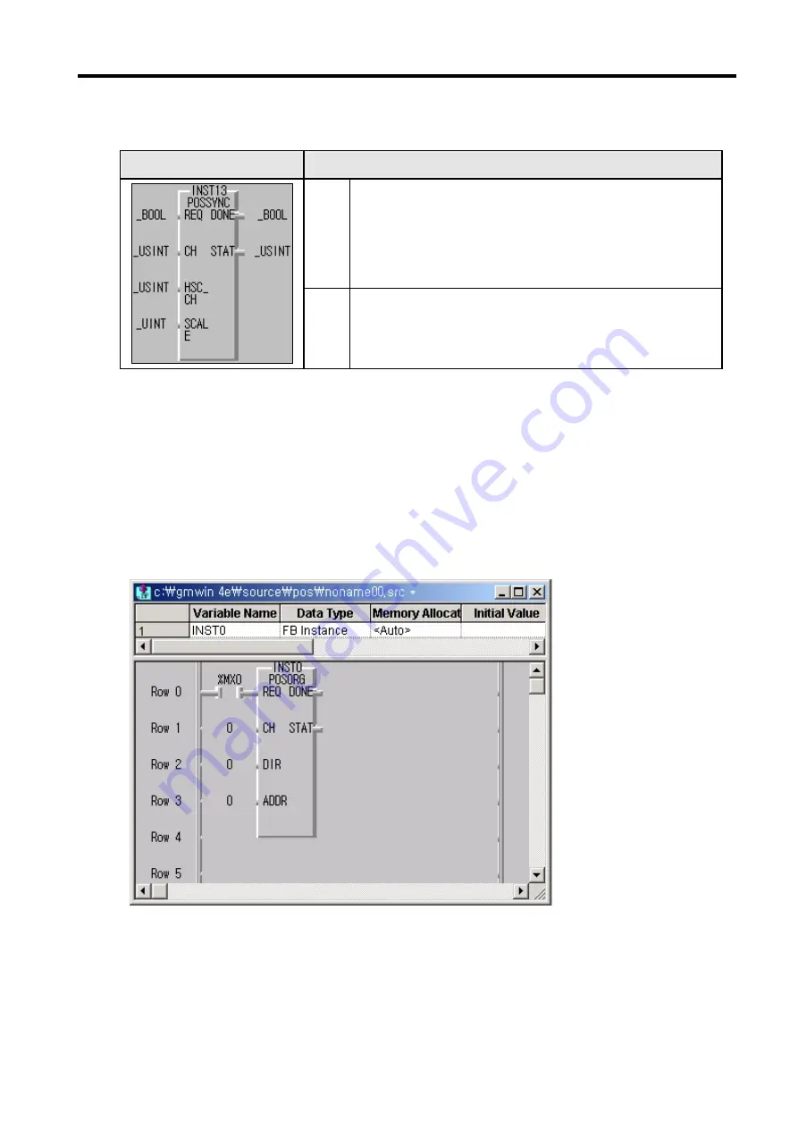
9) Return to origin (POSORG)
Function block
Description
Input
REQ : Execute POSORG function block
CH: Sets the channel (0 ~ 1)
HSC_CH: Sets POSORG input channel (0~3)
SCALE: Sets the scale (0 ~ 100%)
Output
DONE: Turns On after the function block is executed without error, and
turns Off if an error occurs or there is no execution command.
STAT: Displays error status
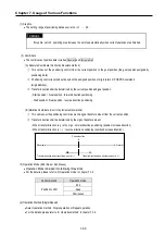
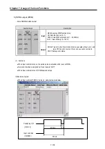
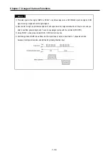
(1)
Functions
•
When input condition turns on, corresponding origin return operation starts (Rising edge trigger)
•
After operation, current address is preset to designated origin address.
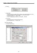
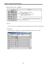
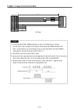
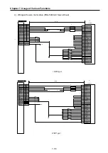
(2)
Example program
•
When input condition
(%MX000)
turns on, Ch. 0 operates return to origin function to the DIR (designated direction).
•
After return to origin operation, the position address becomes 0 (ADDR designated value).
Summary of Contents for GLOFA G7M-DR20U
Page 28: ...Chapter 4 Names of Parts 4 3 2 G7M DRT60U N 3 G7M DT60U N 4 G7M DT60U P...
Page 29: ...Chapter 4 Names of Parts 4 4 5 G7M DR60U DC 6 G7M DRT60U N DC 7 G7M DT60U N DC...
Page 31: ...Chapter 4 Names of Parts 4 6 3 G7M DT40U N 4 G7M DT40U P 5 G7M DR40U DC...
Page 32: ...Chapter 4 Names of Parts 4 7 6 G7M DRT40U N DC 7 G7M DT40U N DC 8 G7M DT40U P DC...
Page 33: ...Chapter 4 Names of Parts 4 8 4 1 3 30 point main unit 1 G7M DR30U 2 G7M DRT30U N 3 G7M DT30U N...
Page 34: ...Chapter 4 Names of Parts 4 9 4 G7M DT30U P 5 G7M DR30U DC 6 G7M DRT30U N DC...
Page 36: ...Chapter 4 Names of Parts 4 11 2 G7M DRT20U N 3 G7M DT20U N 4 G7M DT20U P...
Page 37: ...Chapter 4 Names of Parts 4 12 5 G7M DR20U DC 6 G7M DRT20U N DC 7 G7M DT20U N DC...
Page 38: ...Chapter 4 Names of Parts 4 13 8 G7M DT20U P DC...
Page 159: ...Chapter 7 Usage of Various Functions 7 52 c Program...
Page 183: ...Chapter 7 Usage of Various Functions 7 76 c Program...
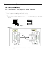
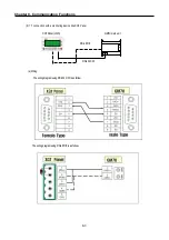
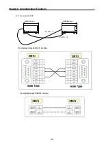
Page 253: ...Chapter 8 Communication Functions 8 27 b When uses Ch 1 Built in RS 485...
Page 356: ...Appendix 1 System Definitions App1 9 6 Position Parameter...
Page 357: ...Appendix 1 System Definitions App1 10 7 High Speed Counter Parameter...


