


Chapter 2. System Configuration
2-3
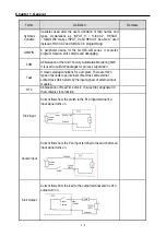
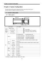
(3) 1:1 communication between HMI andGM7U via RS-485 built-in port
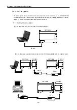
2) 1:N communication system
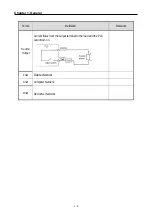
This method can connect a computer to multiple main units up to a maximum of 32 stations.
(1) Via RS-422 Cnet I/F module
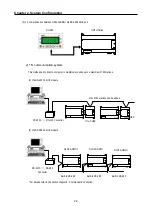
(2) Via RS-485 Cnet I/F module
G7L-CUEC
RS-232C
⇔
RS-422 Converter
Max. of 32 stations can be added
G7L-CUEC
* For details, refer to the section chapter 8. ‘Communication Function’.
GLOFA-GM7U
RS-232C
⇔
RS-485
Converter
Built-in RS-485
Built-in RS-485
Built-in RS-485
GLOFA-GM7U
GLOFA-GM7U
RS-485
GM7U Series
Summary of Contents for GLOFA G7M-DR20U
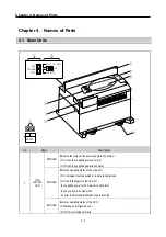
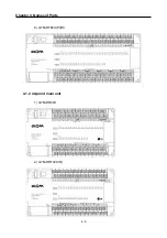
Page 28: ...Chapter 4 Names of Parts 4 3 2 G7M DRT60U N 3 G7M DT60U N 4 G7M DT60U P...
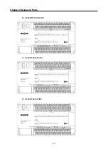
Page 29: ...Chapter 4 Names of Parts 4 4 5 G7M DR60U DC 6 G7M DRT60U N DC 7 G7M DT60U N DC...
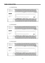
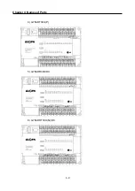
Page 31: ...Chapter 4 Names of Parts 4 6 3 G7M DT40U N 4 G7M DT40U P 5 G7M DR40U DC...
Page 32: ...Chapter 4 Names of Parts 4 7 6 G7M DRT40U N DC 7 G7M DT40U N DC 8 G7M DT40U P DC...
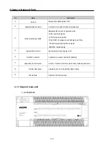
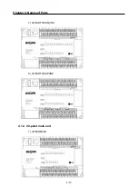
Page 33: ...Chapter 4 Names of Parts 4 8 4 1 3 30 point main unit 1 G7M DR30U 2 G7M DRT30U N 3 G7M DT30U N...
Page 34: ...Chapter 4 Names of Parts 4 9 4 G7M DT30U P 5 G7M DR30U DC 6 G7M DRT30U N DC...
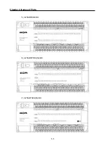
Page 36: ...Chapter 4 Names of Parts 4 11 2 G7M DRT20U N 3 G7M DT20U N 4 G7M DT20U P...
Page 37: ...Chapter 4 Names of Parts 4 12 5 G7M DR20U DC 6 G7M DRT20U N DC 7 G7M DT20U N DC...
Page 38: ...Chapter 4 Names of Parts 4 13 8 G7M DT20U P DC...
Page 159: ...Chapter 7 Usage of Various Functions 7 52 c Program...
Page 183: ...Chapter 7 Usage of Various Functions 7 76 c Program...
Page 253: ...Chapter 8 Communication Functions 8 27 b When uses Ch 1 Built in RS 485...
Page 356: ...Appendix 1 System Definitions App1 9 6 Position Parameter...
Page 357: ...Appendix 1 System Definitions App1 10 7 High Speed Counter Parameter...


