


WavePro 7Zi
495
WP700Zi-OM-E-RevA
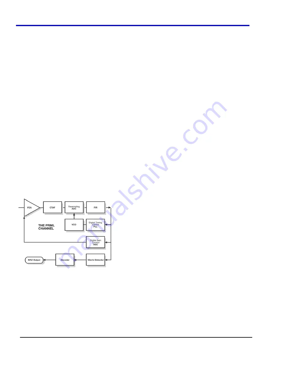
Resampling ADC
Because the DDA data is already digital, this simply interpolates between DDA samples to produce a digital value
at the channel sample time.
Finite Impulse Response (FIR)
In addition to the continuous time analog filter (CTAF), there is normally an FIR filter following the analog-to-digital
converter at the PRML channel’s sample rate. Its purpose is to ‘adapt’ and fine-tune equalization. The DDA’s 21-
tap FIR has coefficients that can be set using remote commands. The tap weights can be asymmetric to minimize
delay through the filter. Extra delay will reduce the stability of our control loops for sampling phase and automatic
gain control.
If the coefficients as entered sum to > 1 they are renormalized to sum to 1.0; if they sum to < 0.1 as entered they
are rejected. Other than that, there are no restrictions on the tap weights.
In many channel chips, the FIR equalization filter is adaptive. However, the DDA does not change the values set
by the user.
Phase Locked Loop (PLL)
Correct operation of any PRML system also depends on the taking of readback signal samples at exact "focus"
positions. Shifting the clock slightly from the correct position is enough to distort sample values.
A clock recovery circuit, Phase Locked Loop (PLL), adjusts the phase of the oscillator, based on the value of the
phase error. This is usually done in a feedback circuit.
The phase-error function is calculated in the phase detector circuit and is equal to zero in the correct clock
position. When the signal is correct, the error signal is equal to zero, and oscillator frequency and phase remain in
exactly the correct position. If for some reason the phase of the input signal and that of the oscillator diverge
(owing to instability of disk rotation or noise, for example) the phase-error signal deviates from zero, and the
frequency of the oscillator shifts.
Two main problems have to be resolved in the clock recovery circuit. One is the initial fast-phase acquisition: prior
to a reading of the pattern, it is necessary to align the clock to the correct position of the pattern. The other is
tracking: the following of relatively slow instabilities of the disk rotational speed. In order to avoid fast, noisy phase
shifts, and to provide system stability, the phase-error signal is integrated by an integrator.
Automatic Gain Control (AGC)
The phase and gain steering algorithm in the DDA’s channel emulation (AGC) will adjust for changes in the signal
after VCO Synch. Read gate tells us where to start looking at the VCO Synch.
Phase is essentially the timing of when a sample is taken, while gain is the levels that are being searched for as
+1 and -1. Thus, when a sample larger than the ideal value is taken, the level looked for by the emulation is
increased. The screen below shows an example of phase and gain steering.
To start the AGC, we must find the maximum and minimum levels in the VCO Synch, and then initialize the levels
to be searched. Thus, if the pulses are exactly the desired shape, then 1 and -1 will be where expected, with the
other levels symmetrically spaced in between.
Summary of Contents for DDA 7 Zi series
Page 1: ...Operator s Manual WavePro SDA and DDA 7 Zi Series Oscilloscopes ...
Page 2: ... L R R H HUD RU D D ...
Page 41: ...Operator s Manual WP700Zi OM E RevA 40 The detachable WavePro Zi front panel ...
Page 376: ...WavePro 7Zi 375 WP700Zi OM E RevA Absolute Offset Relative ...
Page 439: ...Operator s Manual WP700Zi OM E RevA 438 ...
Page 440: ...WavePro 7Zi 439 WP700Zi OM E RevA ...
Page 544: ...Thank you for purchasing a WavePro SDA or DDA 7 Zi Oscilloscope ...


