


Operator's Manual
WP700Zi-OM-E-RevA
418
Clock Recovery Theory
An accurate reference clock is central to all of the measurements performed by the SDA. The recovered clock is
defined by the locations of its crossing points in time. Starting with zero, the clock edges are computed at specific
time intervals relative to each other. A 2.5 GHz clock, for example, will have edges separated in time by 400 ps.
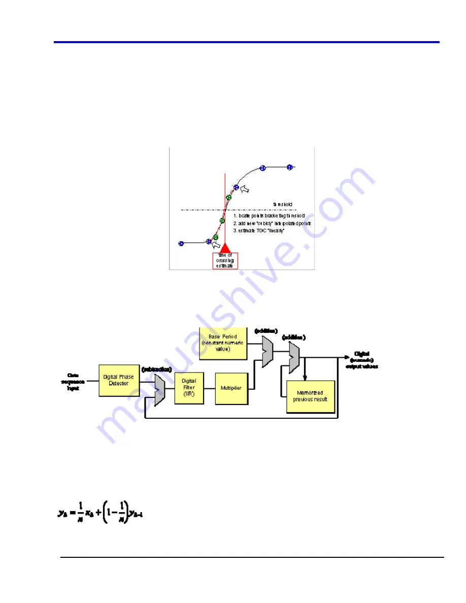
The first step in creating a clock signal is the creation of a digital phase detector. This is simply a software
component that measures the location in time at which the signal crosses a given threshold value. Given the
maximum sampling rate available, 40 GHz, interpolation is necessary in most cases. Interpolation is automatically
performed by the SDA. Interpolation is not performed on the entire waveform; rather, only the points surrounding
the threshold crossing are interpolated for the measurement. A cubic interpolation is used, followed by a linear fit
to the interpolated data, to find the crossing point. This is shown in the following figure .
Figure 5-31. SDA Threshold Crossing Algorithm.
Clock recovery implementation in the SDA is shown in the following figure. This algorithm generates time values
corresponding to a clock at the data rate. The computation follows variations in the data stream being tested
through the use of a feedback control loop that corrects each period of the clock by adding a portion of the error
between the recovered clock edge and the nearest data edge.
Figure 5-32. Clock Recovery Implementation.
As shown in Figure 2, the initial output and the output of the digital phase detector are set to zero. The next time
value output is equal to the nominal data rate. This value is fed back to the comparator on the far left which
compares this time value to the measured time of the next data edge from the digital phase detector. The
difference is the error between the data rate and the recovered clock. This difference is filtered and added to the
initial base period to generate the corrected clock period. The filter controls the rate of this correction by scaling
the amount of error that is fed back to the clock period computation. This filter is implemented in the SDA as a
single-pole infinite impulse response (IIR) low-pass filter. The equation of this filter is:
The value of
y
k
is the correction value for the
k
th
iteration of the computation and
x
k
is the error between the
k
th
data edge and the corresponding clock edge. Note that the current correction factor is equal to the weighted sum
of the current error and all previous correction values. The multiplier value is set to one in the SDA, and the value
Summary of Contents for DDA 7 Zi series
Page 1: ...Operator s Manual WavePro SDA and DDA 7 Zi Series Oscilloscopes ...
Page 2: ... L R R H HUD RU D D ...
Page 41: ...Operator s Manual WP700Zi OM E RevA 40 The detachable WavePro Zi front panel ...
Page 376: ...WavePro 7Zi 375 WP700Zi OM E RevA Absolute Offset Relative ...
Page 439: ...Operator s Manual WP700Zi OM E RevA 438 ...
Page 440: ...WavePro 7Zi 439 WP700Zi OM E RevA ...
Page 544: ...Thank you for purchasing a WavePro SDA or DDA 7 Zi Oscilloscope ...


