158
2
Select “Half Damper Calibration” to access the dialog
box.
3
Press the half-damper pedal, and then release your foot
from the pedal.
4
Press the Done button.
If the adjustment could not be performed correctly, an
error message will be displayed. Please perform the pro-
cedure once again.
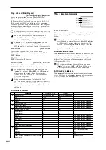
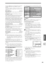
0–2: System Preference
0–2a: System Preference
Bank Map
[KORG, GM(2)]
Specifies the mapping of programs and combinations rela-
tive to Bank Select control change messages (CC#0 upper
byte and CC#32 lower byte).
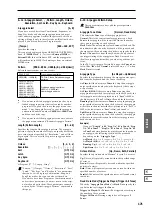
The bank select messages shown in the table below will be
received (R) and transmitted (T) for program banks A–F, G,
g(1)...g(9), g(d), H–N (F is only for the EXB-MOSS option)
and Combination banks A–E, and H–N.
Power On Mode
[Reset, Memorize]
Specifies the condition at power-on.
Reset:
The TRITON Extreme will be in Combination mode
P0: Play, and Combination A000 will be selected.
Memorize:
The location (mode and page) where you were
when the power was last turned off, and the last-selected
program or combination number will be selected.
This function does not memorize the contents of any
parameters that were edited. Before turning off the
power, be sure to write your data or save it in Media
mode.
System Clock
[Internal, S/P DIF]
Specifies the system clock of the TRITON Extreme.
Internal:
The TRITON Extreme will operate with its own
internal clock. Normally you will use this setting.
S/P DIF:
The TRITON Extreme will operate using the sys-
tem clock of the S/P DIF Optical format-compatible device
connected to the S/P DIF IN jack.
The TRITON Extreme’s S/P DIF jacks transmit and
receive only at the 48 kHz sample rate. If “System
Clock
” is set to S/P DIF, and the TRITON Extreme
becomes unable to detect the correct clock because 96
kHz data is being received or a cable has been discon-
nected etc., an error message of “S/P DIF Clock Error!”
will blink in the status bar of the display. Please verify
that the transmitting device is set to the appropriate
clock frequency, and that there is no problem with the
cable. In order for S/P DIF input to work correctly,
make sure that the correct clock is being received and
that the error message has disappeared from the status
bar. Then switch “System Clock” to Internal, and then
back to S/P DIF once again.
If the “System Clock” setting of S/P DIF is stored, and
the correct clock is not being input when the TRITON
Extreme is powered-on, the “S/P DIF Clock Error!”
message will blink in the status bar, and the TRITON
Extreme will not play correctly.
The “System Clock” setting can be stored by the “Write
Global Setting” utility.
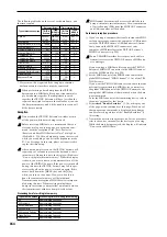
WAVE File Play Level
[Normal, High (+12dB)]
Specifies the playback level when a WAVE file from the
media is played on the TRITON Extreme. This setting
applies only to playback of a WAVE file. This will apply to
the following pages and dialog boxes.
• Program, Combination, and Sequencer page menu
command “Select Directory” 0–3D)
• Sampling page menu command “Select Directory” (0–
1N)
• Media mode directory window (0–1b)
• Media mode Make Audio CD audio track list (0–4b),
page menu command “Insert” (0–4C)
Normal:
The WAVE file will play back at the normal level.
This is the same standard level as when “+12 dB” (Sampling
P2: 2–1c) is off.
High (+12 dB):
Choose this setting if you are playing back a
Wave file on the TRITON Extreme and sending it from S/P
DIF OUT to be recorded on an external digital audio device.
This will raise the digital output level by approximately 12
dB to match the level of the external digital audio device.
Please be aware that the volume of the AUDIO OUTPUT L/
MONO and R, and headphone jacks will also rise at this
time.
Bank
Bank Map: KORG
Bank Map: GM(2)
A
00. 00 R/T
63. 00 R/T
B
00. 01 R/T
63. 01 R/T
C
00. 02 R/T
63. 02 R/T
D
00. 03 R/T
63. 03 R/T
E
00. 04 R/T
63. 04 R/T
F
00. 05 R/T
63. 05 R/T
G,
g(1)...g(9)
121. 00, 121. 01...09 R/T
121. 00, 121. 01...09 R/T
56. 00 R
56. 00 R
00. 00, 00. 01...(XG) R
00. 00, 01. 00...(GS) R
g(d)
120. 00 R/T
120. 00 R/T
62. 00 R
62. 00 R
63. 127 R (
→
Korg MUTE)
H
00. 08 R/T
63. 08 R/T
I
00. 09 R/T
63. 09 R/T
J
00. 10 R/T
63. 10 R/T
K
00. 11 R/T
63. 11 R/T
L
00. 12 R/T
63. 12 R/T
M
00. 13 R/T
63. 13 R/T
N
00. 14 R/T
63. 14 R/T
0–1
0–2a
0–2b
Summary of Contents for TRITON Extreme
Page 1: ...2 E ...
Page 11: ...xii ...
Page 111: ...100 9 5 Page Menu Command 0 1A 0 1I 0 1J Program 9 5A ...
Page 185: ...174 ...
Page 215: ...204 ...
Page 281: ...270 ...
Page 349: ...338 ...
Page 350: ...339 ...
Page 351: ...340 ...
Page 352: ...341 ...
Page 353: ...342 ...

