15
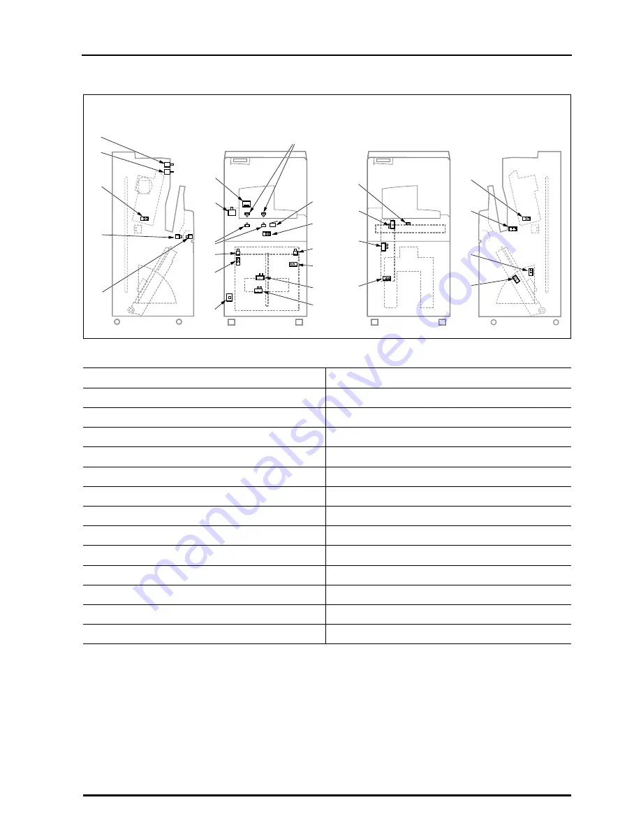
1.3 Layout of Controlling Components
REGIUS MODEL 190 Service Manual Ver.1.00 2004.11.01
1.3.3
Locations of Sensors and Switches
No.
Part Name
No.
Part Name
1
"operation" SW (SW1)
14
Cassette Back Plate Sensor (S21)
2
"erase" SW (SW2)
15
Justi
fi
cation Sensor-R (S4)
3
Peel Sensor-L (S13)
16
Elevator Sensor-HP (S8)
4
Insertion Shutter Close Sensor (S18)
17
Cassette Receive Sensor (S2)
5
Insertion Shutter Open Sensor (S19)
18
Lock-Release Sensor (S1)
6
Bar Code Reader
19
Thermostat (TM1)
7
"eject" SW (SW5)
20
Sync Sensor (S12)
8
Insertion Slot Sensor Emission (LLB1, LLB2)
21
Absorption (Magnetizing) Detect Sensor (S15)
9
Justi
fi
cation Sensor-L (S3)
22
Subscan HP Sensor (S17)
10
Justi
fi
cation HP Sensor (S9)
23
Peel Sensor-Right (S14)
11
Interlock SW (SW3)
24
Ejection Shutter Close Sensor (S20)
12
Insertion Slot Sensor Receptor (LPB1, LPB2)
25
Feed Escape Position Sensor (S11)
13
Insertion Guide SW (SW4)
26
Feed HP Sensor (S10)
1
7
19
22
23
24
26
25
20
21
13
14
15
16
17
18
8
9
10
11
12
2
3
4
5
6
Left
Front
Right
Front
Summary of Contents for REGIUS 190
Page 7: ...VI REGIUS MODEL 190 Service Manual Ver 1 00 2004 11 01...
Page 13: ...Blank...
Page 27: ...xx REGIUS MODEL 190 Service Manual Ver 1 00 2004 11 01...
Page 28: ...Chap 1 Overview...
Page 29: ...Blank Page...
Page 43: ...16 1 3 Layout of Controlling Components REGIUS MODEL 190 Service Manual Ver 1 00 2004 11 01...
Page 45: ...Blank Page...
Page 52: ...Chap 2 Disassembly and Reassembly...
Page 53: ...Blank Page...
Page 118: ...Chap 3 Maintenance Adjustment...
Page 119: ......
Page 154: ...Chap 4 Troubleshooting...
Page 155: ......
Page 194: ...A Appendix...
Page 195: ......
Page 220: ...0676 55030 B 0412TE...


