6A – 34
GENERAL ENGINE MECHANICAL
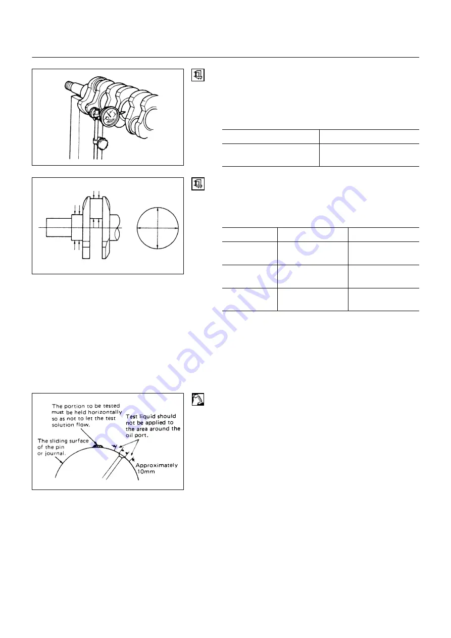
3. Run-out
1) Carefully set the crankshaft on the V-blocks.
Slowly rotate the crankshaft and measure the runout.
If the crankshaft runout exceeds the specified limit, the
crankshaft must be replaced.
Run-Out
mm (in)
Standard
Limit
0.05 (0.0020)
or less
0.08 (0.0031)
Measure the diameter and the uneven wear of main
journal and crank pin.
If the crankshaft wear exceeds the specified limit,
crankshaft must be replaced.
mm (in)
Standard
Limit
Main journal
diameter
69.917-69.932
(2.7526 - 2.7532)
69.91 (2.7524)
Crank pin
diameter
52.915 - 52.930
(2.0833)
52.90 (2.0843)
Uneven wear
limit
0.05 (0.0020)
or less
0.08 (0.0031)
Crankshaft inspection
Inspect the surface of the crankshaft journals and crank
pins for excessive wear and damage.
Inspect the oil seal fitting surfaces for excessive wear and
damage.
Inspect the oil ports for obstructions.
Crankshaft tufftriding inspection
The portion to be tested must be held horizontally so as
not let the test solution flow.
Test liquid should not be applied to the area around the oil
port.
The sliding surface of the pin or journal.
Approximately 10mm
NOTE:
To increase crankshaft strength, Tufftride Method
(Soft nitriding) has been applied. Because of this, it is
not possible to regrind the crankshaft surfaces.
1. Use an organic cleaner to thoroughly clean the
crankshaft. There must be no traces of oil the surfaces
to be inspected.
2. Prepare a 5-10% solution of ammonium cupric
chloride (dissolved in distilled water).
6A-34-1.tif
6A-34-2.tif
6A-34-3.tif
Summary of Contents for NHR 4J Series
Page 1: ...WORKSHOP MANUAL NHR NKR NPR ENGINE 4J SERIES SECTION 6...
Page 2: ...MEMO...
Page 58: ...00 54 SERVICE INFORMATION Cooling System and Lubrication System N m kg m lb ft...
Page 60: ...00 56 SERVICE INFORMATION N m kg m lb ft 036LX003 tif...
Page 61: ...SERVICE INFORMATION 00 57 Engine Electricals N m kg m lb ft 0056 1 tif...
Page 62: ...00 58 SERVICE INFORMATION Engine Fuel N m kg m lb ft 0057 1 tif...
Page 63: ...SERVICE INFORMATION 00 59 Engine Mounting Bracket N m kg m lb ft 0058 1 tif...
Page 67: ...SERVICE INFORMATION 00 63 MEMO...
Page 325: ...6C 66 ENGINE FUEL MEMO...
Page 333: ...6D1 8 ENGINE ELECTRICAL MEMO...
Page 335: ...6D2 2 STARTING SYSTEM STARTING CIRCUIT 6D2 2 1 tif...
Page 347: ...6D3 2 CHARGING SYSTEM Generator 6D3 2 1 tif 6D3 2 2 tif...
Page 348: ...CHARGING SYSTEM 6D3 3 CHARGING CIRCUIT 6D3 3 1 tif...
Page 367: ...6D3 22 CHARGING SYSTEM MEMO...
Page 369: ...6D6 2 QOSII PREHEATING SYSTEM SYSTEM DIAGRAM QOS II Timing Chart 6D6 2 1 tif 6D6 2 2 tif...
Page 373: ...6D6 6 QOSII PREHEATING SYSTEM MEMO...
Page 375: ...6D7 2 QOSIII PREHEATING SYSTEM SYSTEM DIAGRAM QOS II Timing Chart 6D7 2 1 tif 6D7 2 2 tif...
Page 376: ...QOSIII PREHEATING SYSTEM 6D7 3 QOS III FLOW CHART 6D7 3 1 tif...
Page 377: ...6D7 4 QOSIII PREHEATING SYSTEM QOS III BLOCK CHART 6D7 4 1 tif...
Page 381: ...6D7 8 QOSIII PREHEATING SYSTEM MEMO...
Page 387: ...6E 6 EXHAUST GAS RECIRCULATION EGR SYSTEM MEMO...
Page 393: ...6F 6 ENGINE EXHAUST MEMO...
Page 406: ...No HGSTG WE 661 PRINTED IN JAPAN...


