


INTEC GmbH
22/12/2016
Lift controller MLC 8000
Operating manual V2.0
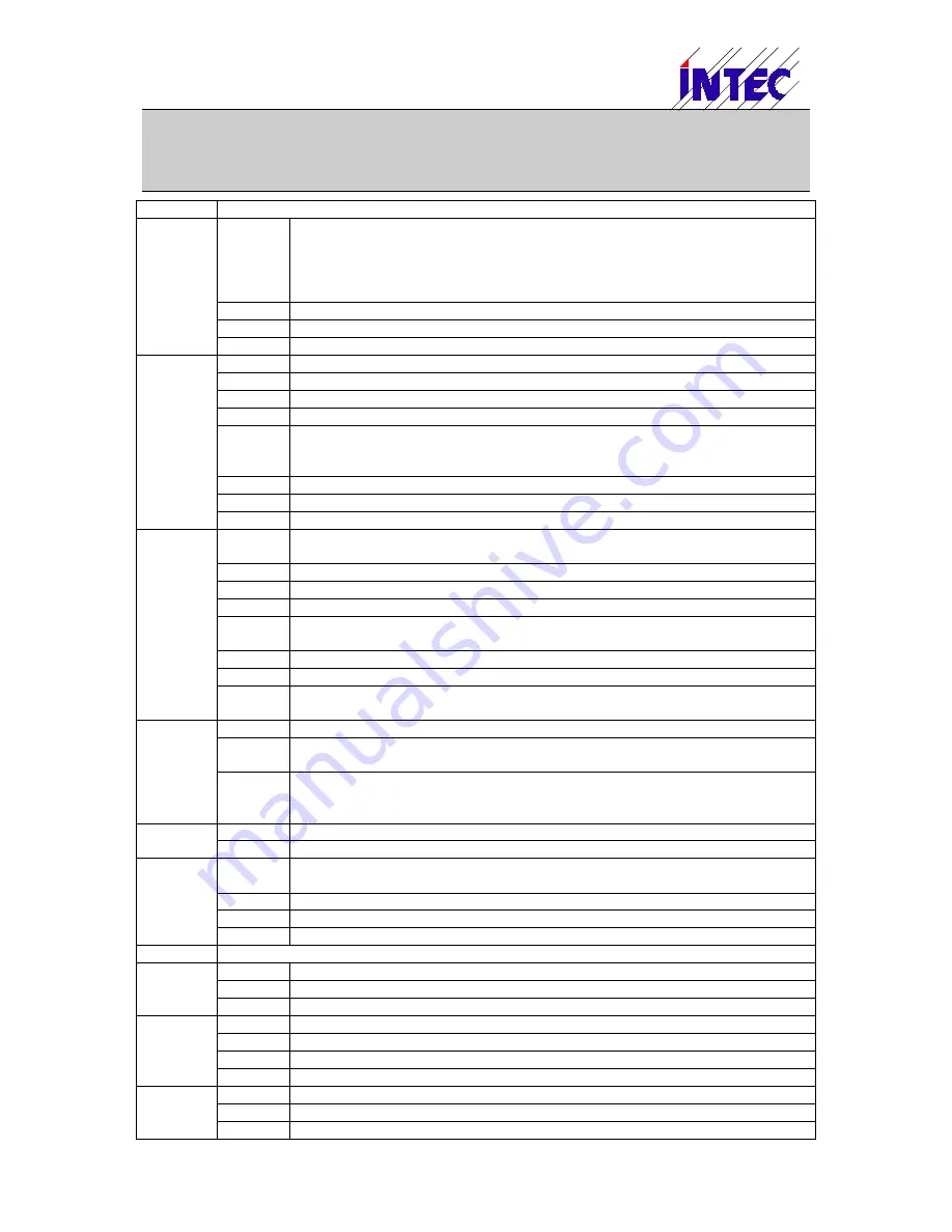
Position
Function
RC1/
SLOW
Relay KM3 (MCU Output 3): N.O. contact; Default: Main contactor (Running
contactor)
Note: For lifts with safety unit for moving with open doors the relay KM3 must
always be used as running contactor even if nothing is connected to KM3,
because by a second contact of KM3 the door zone bypass will be enabled.
DOWN
Relay KM2 (MCU Output 2): N.O. contact; Default: Downwards contactor
FAST
Relay KM1 (MCU Output 1): N.O. contact; Default: Fast contactor
V2*, V2
Relay KM1 (MCU Output 1): Additional, potential free N.O. contact
XM5
L-SAF
Connection for end of safety circuit to switch contactors
N-SAF
Neutral safety circuit (Output to connnecting neutral to contactors)
SDSL
State input safety line shaft doors (MCU Input 12), for 110V to 230V AC
CDSL
State input safety line car doors (MCU Input 11), for 110V to 230V AC
RDSL
State input safety line revolving shaft doors (MCU Input 10), for 110V to 230V
AC
PSL
State input primary safety line (MCU Input 9), for 110V to 230V AC
N
Neutral safety circuit (Input)
CSUP
Input for contactor supervision (MCU Input 13), for 110V to 230V AC
XM6
+24S
24V power supply output to safety unit SRU; Imax.=0.5A (electronic fuse on
MCU).
0V
0V power supply for safety unit SRU
ZONE
Feedback signal from safety unit SRU (lift in door zone)
MSI
Output door zone switch MSI to safety unit SRU channel A
ULSI
Output 2. door zone signal to safety unit SRU channel B (generated by
software, logical OR of USI and LSI signals)
n.c.
Not connected
n.c.
Not connected
SRO
Safety circuit door zone bypass for moving with open doors (output of safety
unit SRU)
XM7
0V
0V – Power supply (to trailing cable)
+24A
Battery buffered 24V power supply (to trailing cable); Imax. = 1.0A (electronic
fuse on MCU)
+24C
24V – Power supply (to trailing cable); Imax. = 1.8A (electronic fuse on MCU).
If larger power is necessary the trailing cable should be connected directly to
the 24V power supply unit.
XM8
0V
0V – Power supply input for MCU
+24IN
+24V – Power supply input for MCU
XM9
+12V
Battery buffered 12V - Power supply (e.g. for Intercom); Imax. = 0.5A; overload
and short-circuit-proof
0V
0V – Power supply
0V
0V – Connection for negative pol of external 12V battery
BA+
Connector for positive pol of external 12V battery (battery charging)
XM10
Connector for handheld terminal (No USB connector!)
XM11
0V
Connetor for shield CAN bus cable (only MCU version 1.2)
C1-
Control bus (CAN-Bus 1) – Low-Signal
C1+
Control bus (CAN-Bus 1) – High-Signal
XM12
0V
0V – Power supply
0V
Connetor for shield CAN bus cable
C2-
Shaft bus (CAN Bus 2) – Low-Signal
C2+
Shaftbus (CAN Bus 2) – High-Signal
XM13
0V
0V – Power supply for encoder
B+
Encoder Channel B+; 5V oder 10..30V (see Jumper JP4+JP5)
B-
Encoder Channel B- (inverted signal); 5V or 10..30V (see Jumper JP4+JP5)


