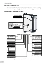
1 Product Information
- 18 -
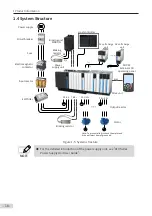
1.4 System Structure
Electromagnet
ic
contactor
Circuit breaker
Power supply
Input reactor
Braking
resistor
EMC
filter
R S T
P(+)
W
V
U
BR
+
-
+
BR
Braking unit
MDBUN
Note
: To prevent electric shock, the motor and
drive unit must be well grounded.
Motor
Output reactor
Fuse
SOP
-20
External
LCD
operating panel
PE
W
V
U
PE
Host controller
Braking resistor
PE
…
Power
supply unit
Drive unit
(+)
(-)
…
(+)
(-)
DC soft charge
unit
DC soft charge
unit
RJ45
Figure 1-5
System structure
NOTE
◆
For the detailed introduction of the power supply unit, see "810 Series
Power Supply Unit User Guide".

