3 Wiring
- 41 -
3.3 Control Circuit Wiring
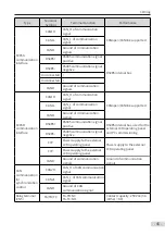
3.3.1 Descriptions of Control Terminals (Single-axis)
CAN
2H
CAN
2L
CGND
C485+
C485-
S1
DI1
DI2
DIO
1
DIO
2
24V
OP
COM
A+
A-
B+
B-
Z+
Z-
5V
PGND
15V
+10V
GND
AI1
AI2
AO
1
1
2
3
4
5
6
7
8
9
CN
1
CN
4
CN3
CN
6
CN
2
12
3
TA
TB
TC
CN
5
S2
12
34
DIP switch
DI/
DO terminal
AI/
AO terminal
Encoder
/
PG card terminal
DP communication terminal/
23
-bit encoder
External CAN and RS
485 terminal
Relay terminal
DIP switch
Control circuit terminals
STO
2
GND
2
1
GND
1
STO terminal
RJ45
communication
terminal
RJ45A
RJ45B
6
7
8
9
10
11
12
13
14
1
2
3
4
5
CN
6
Resolver terminal
15
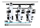
Figure 3-3 Control circuit terminal arrangement of the drive unit (single-axis 1.5–160 kW
booksize unit)
CAN
2H
CAN
2L
CGND
C485+
C485-
S1
DI1
DI2
DIO
1
DIO
2
24V
OP
COM
A+
A-
B+
B-
Z+
Z-
5V
PGND
15V
+10V
GND
AI1
AI2
AO
1
1
2
3
4
5
6
7
8
9
CN
1
CN
4
CN3
CN
6
CN
2
12
3
TA
TB
TC
CN
5
S2
12
34
Control circuit
terminals
STO
2
GND
2
1
GND
1
RJ45A
RJ45B
DC24V
GND
24V_
EXT
0V_
EXT
KIN
1
KOUT
KIN
2
STO interface
RJ45 communication
interface
DIP switch
DI/
DO terminal
AI/
AO terminal
Encoder
/
PG
card terminal
DP communication
interface
External CAN and RS
485
interface
Relay terminal
DIP switch
Figure 3-4 Control circuit terminal arrangement of the drive unit (single-axis 90–355 kW
vertical tower unit)

