3 Wiring
- 38 -
3 Wiring
This chapter describes only the electrical installation of the drive unit. For the electrical
installation of the power supply unit, see "810 Series Power Supply Unit User Guide".
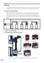
3.1 Typical System Wiring
When using the MD810 at customer sites, if a drive unit fails and needs a replacement,
the drive unit supports independent power-on and power-off without having to shut
down the power supply unit. It is recommended to install a DC soft charge unit with
each drive unit. For information of wiring, see Figure 3-6 which is on the last page of this
chapter.
WARNING
The drive unit has a fuse. Independent power-on without a DC soft charge unit is
inhibited because such power-on will damage the drive unit.
Contactor KM or
other air switch
MD810
power
supply
unit
MD810
drive unit
+
-
DC bus
MD810
power
supply
unit
MD810
drive unit
+
-
DC bus
+
+
+
+
-
-
-
-
Contactor KM or
other air switch
MD810
power
supply
unit
MD810
drive unit
+
-
DC bus
+
+
-
-
DC soft charge
unit
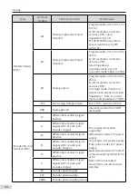
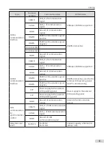
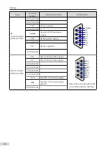
3.2 Main Circuit Wiring
3.2.1 Descriptions of Power Terminals
MD810-50M4T1.5
G
to
MD810-50M4T
7
.5
G
MD810-50M4T11
G
to
MD810-50M4T
37G
MD810-50M4T45
G
to
MD810-50M4T
75G
21
21
18
U
V
W
13
.9
13
.9
9.0
U
V
W
MD810-50M4T90
G
to
MD810-50M4T110
G
33
33
28
U
V
W
Main circuit
terminal
24 V power supply
24V
COM
24V
COM
40
44.5
U
V
W
40
U
V
W
44
44
44.5
MD810-50M4T
132G
to
MD810-50M4T160
G
Figure 3-1
Power terminal arrangement and size of the drive unit (single-axis)

