background image

1 Product Information                                                                                                                      


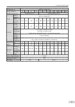
- 14 -

Voltage Rating

380 VAC to 480 VAC

Model: 

MD81050M4TxxxGxxx(W)

1.5 2.2

3.7

5.5

7.5

11 15 18.5 22

30 37

45

55

75

Input

Input Voltage

Three-phase 537 VDC to 679 VDC

Input Current, 

DC (A)

4.9

7

12

17

22

31

40 46 55

73

90 105 129

172

Output 

Output 

Current, AC 

(A)

3.8

5.1 9

13 17

25

32 37

45 60

75

91 112 150

Carrier 

Frequency

V/F control: 0.8 kHz to 12 kHz

SVC/FVC: 2 kHz to 10 kHz

Automatically adjusted based on heatsink temperature

Output 

Voltage

0 VAC to 480 VAC

Output 

Frequency

V/F control: 0 Hz to 500 Hz

SVC/FVC: 0 Hz to 500 Hz

Applicable 

Motor

kW

1.5 2.2

3.7

5.5

7.5

11 15 18.5 22

30 37

45

55

75

HP

2

3

5

7.5

10 15 20 25

30

40 50 60

70

100

Thermal 

Design

Thermal 

Design Power 

(W)

47

59

76 127

155 249 294

343

425 526 669

817 1033 1379

Air Flow (CFM) 10 10 10 10 10 40 40 55 65

75

105

130 175

195

Overvoltage Category

OVCIII 

Pollution Degree

PD2

IP Rating

IP20

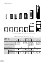
Table 1-2 Technical data of the drive unit (single-axis, 90–355 kW)

Voltage Class

380 VAC to 480 VAC

Model: MD810-

50M4TxxxGxxx(H)

90

110

132

160

90 110

132

160 200 250

315 355

Booksize Unit

Vertical Tower Unit

Physical Dimensions

(mm)

[H]: 350 mm

[H1]: 384 mm 

[H2]: 400 mm

 [W]: 300 mm 

[W1]: 150 mm 

[D]: 305 mm

[H]: 

750 mm

[H1]: 

730 mm

[H2]: 

770 mm

 [W]: 

180 mm 

[W1]: 

125 mm 

[D]: 

441.5 mm

[H]: 

900 mm

[H1]: 

885 mm 

[H2]: 

920 mm

 [W]: 

180 mm 

[W1]: 

125 mm 

[D]: 

466.5 mm

[H]:  1395 mm

[H1]: 1365 mm

[W]:  230 mm

[W1]:  100 mm

[W2]:  75 mm

[D]:   633 mm

Mounting Hole  (mm)

Φ7

Φ8

Φ9

Weight (kg)

24.2 24.2

25.2

25.2

35

35

45

45

100 100 100 100

Summary of Contents for MD810 Series

Page 1: ...User Guide MD810 Series Standard Drive Multidrive System A04 Data code 19010518 User Guide...

Page 2: ...ing hoisting and other industries The MD810 series drive unit must be used with an MD810 power supply unit This guide only describes the product information installation communication troubleshooting...

Page 3: ...Directives Standard CE EMC directives 2014 30 EU EN 61800 3 LVD directives 2014 35 EU EN 61800 5 1 RoHS directives 2011 65 EU EN 50581 TUV EN 61800 5 1 NOTE The above EMC directives are complied with...

Page 4: ...ripheral electric elements for MD810 series drive and Table 3 2 Recommended cable dimensions and tightening torque December 2018 A03 Added information of the 300 mm booksize model April 2019 A04 Added...

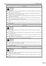
Page 5: ...o responsibility for any personal injuries or property damage caused by improper usage Safety Levels and Definitions DANGER indicates that failure to comply with the notice will result in severe perso...

Page 6: ...r equipment or materials that may harm or have negative impacts on this equipment WARNING Use professional loading and unloading equipment to carry large scale or heavy equipment When carrying this eq...

Page 7: ...mply will result in an electric shock Before wiring cut off all equipment power supplies Wait at least 10 minutes before further operations because residual voltage exists after power off Make sure th...

Page 8: ...tion Failure to comply will result in an electric shock Do not remove any part of the equipment during operation Failure to comply will result in an electric shock Do not touch the equipment shell fan...

Page 9: ...cording to the product warranty agreement When the equipment is faulty or damaged require professionals to perform troubleshooting and repair by following repair instructions and keep a repair record...

Page 10: ...on the equipment For safe equipment operation and maintenance comply with safety signs on the equipment and do not damage or remove the safety labels The following table describes the safety signs Sa...

Page 11: ...nce Requirements 20 2 1 2 Backplate Hole Size 22 2 2 Installation 23 2 2 1 Installation Methods 23 2 2 2 Installation of the Drive Unit 24 2 2 3 Cabinet Installation 29 2 2 4 Installation of the DC So...

Page 12: ...57 4 3 External LCD Operating Panel 58 4 3 1 Appearance and Display 58 5 Quick Commissioning 60 6 Troubleshooting 71 6 1 Fault Display and Solutions 71 6 2 Fault Codes and Solutions 72 6 3 Common Sym...

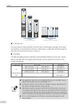
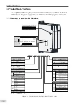
Page 13: ...s None Mark Optional Extension Part None 0 1 Mark Optional Communication Part Built in RS485 and CAN 0 Mark Optional Functional Part 0 1 Mark HeatDissipation None 1 5 160 kW booksize unit H 90 355 kW...

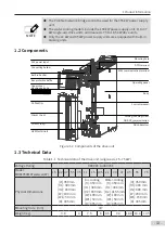
Page 14: ...W terminals Bus protective baffle Connecting busbar Cable clip Shield grounding screw Upper cover Machine barcode XXXXXXXXXXXXXXXXX XX810 50M4TXXX XX 16 bit manufacturing SN Product model Figure 1 2 C...

Page 15: ...55 75 HP 2 3 5 7 5 10 15 20 25 30 40 50 60 70 100 Thermal Design Thermal Design Power W 47 59 76 127 155 249 294 343 425 526 669 817 1033 1379 Air Flow CFM 10 10 10 10 10 40 40 55 65 75 105 130 175 19...

Page 16: ...uency kHz V F control 0 8 kHz to 6 kHz SVC FVC 2 kHz to 6 kHz Automatically adjusted based on heatsink temperature Output Voltage 0 VAC to 480 VAC Output Frequency V F control 0 to 500 Hz SVC FVC 0 to...

Page 17: ...xis Table 1 3 Technical data of the drive unit dual axis Voltage Class 380 VAC to 480 VAC Model MD810 50M4TDxxxGxxxW 1 5 2 2 3 7 5 5 7 5 11 15 18 5 Physical Dimensions mm H 350 mm W 50 mm H1 384 mm D...

Page 18: ...age 0 VAC to 480 VAC Output Frequency V F control 0 to 500 Hz SVC FVC 0 to 500 Hz Applicable Motor kW 1 5 2 2 3 7 5 5 7 5 11 15 18 5 HP 2 3 5 7 5 10 15 20 25 Thermal Design Thermal design power W 90 1...

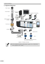
Page 19: ...To prevent electricshock the motor and drive unit must be well grounded Motor Output reactor Fuse SOP 20 External LCD operating panel PE W V U PE Host controller Braking resistor PE Power supply unit...

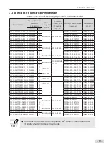
Page 20: ...M4T90GXXX FWH 500A 1 HST 6004 MD OCL 250 0 028 4T 1 RWK 305 182 KS MD810 50M4T110GXXX FWH 600A 1 MD OCL 250 0 028 4T 1 RWK 305 230 KS MD810 50M4T132GXXX FWH 700A 1 HST 7004 MD OCL 330 0 021 4T 1 RWK 3...

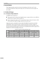
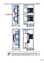
Page 21: ...mm and 230 mm width are larger than the booksize format Single and dual rack installation is supported for the MD810 series drive unit When installing two racks of booksize units one above the other a...

Page 22: ...oksize units in dual rack installation S2 S1 2200 600 500 600 Figure 2 2 Heat dissipation clearances for the large power supply unit vertical tower format NOTE The vertical tower units are designed to...

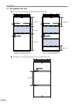
Page 23: ...e Dimensions of mounting holes for the booksize unit 35 mm 35 mm 300mm 300 mm 50 mm 384 mm 35 mm 35 mm 300 mm 300 mm 50 mm Single rack installation Dual rack installation Dimensions of mounting holes...

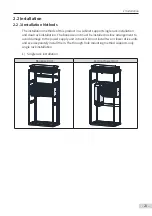
Page 24: ...ion and dual rack installation The booksize unit must be installed in close arrangement to avoid damage to the power supply unit in transit Do not install two or fewer drive units and even separately...

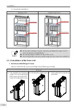
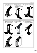
Page 25: ...on Do not separately install two or fewer drive units The through hole mounting method supports only single rack installation 2 2 2 Installation of the Drive Unit 1 Removal and Refitting of Covers Rem...

Page 26: ...inal cover to release the cover 6 Remove the power terminal cover Refitting 1 Locate the power terminal cover at its latch position and fix it 2 Install the operating panel 3 Locate the upper cover at...

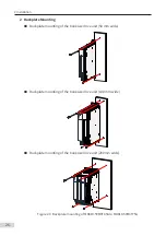
Page 27: ...Backplate mounting of the booksize drive unit 50 mm wide Backplate mounting of the booksize drive unit 100 mm wide Backplate mounting of the booksize drive unit 200mm wide Figure 2 3 Backplate mounti...

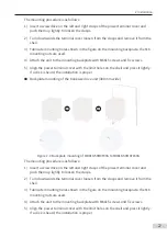
Page 28: ...If a click is heard the installation is proper Backplate mounting of the booksize drive unit 300 mm wide Figure 2 4 Backplate mounting of MD810 50M4T90G to MD810 50M4T160G The mounting procedure is as...

Page 29: ...the vertical tower drive unit 180 mm wide Figure 2 5 Backplate mounting of MD810 50M4T90G to MD810 50M4T160G 3 Through hole mounting Through hole mounting brackets 1 1 2 2 3 3 4 4 1 1 2 2 3 3 4 4 1 Up...

Page 30: ...backplate Step 2 Remove the covers Step 3 Hang the units with the pre installed screws Step 4 Install the EMC grounding aluminum bar To ensure proper grounding of the entire system equipotential inst...

Page 31: ...s Turnoverandconnect NOTE Before connecting the built in busbar remove the left and right bus protective baffles in the top cover with tools such as nipper pliers diagonal pliers The following figure...

Page 32: ...ep 7 Connect the busbar inside the cabinet and wire the common bus power terminals Step 8 Connect cables to the control circuit terminals and PE cable Step 9 Install the covers Step 10 Install the ven...

Page 33: ...net by using the lifting holes e with hoisting equipment Step 2 Tighten the screw d to fix the drive unit Step 3 Install the terminal plug c for the external IO and control power supply Step 4 Connect...

Page 34: ...5 kW c d a b Step 1 Put a ramp a before the cabinet Step 2 Push the drive unit into the cabinet along the ramp Step 3 Tighten the fixing screws b and c for the drive unit Step 4 Connect all control ca...

Page 35: ...6 INOV SU 30 INOV SU 60 INOV SU 100 INOV SU 170 DC soft charge unit installation NOTE Pay attention to the connection of the DC breaker in the preceding figure HST 6004 HST 7004 and drive unit instal...

Page 36: ...ompleted look 7 Reinstall the functional assembly onto the base of HST 6004 and connect the corresponding DC soft charge unit onto the model terminal fix the terminal on the HST 6004 rear and the nega...

Page 37: ...2 Installation 36 External 24 V power supply Connect with the drive unit terminal Figure e Figure f Figure g...

Page 38: ...2 Installation 37 Figure h Figure i Figure 2 7 HST 6004 HST 7004 DC soft charge unit installation...

Page 39: ...a fuse Independent power on without a DC soft charge unit is inhibited because such power on will damage the drive unit Contactor KM or other air switch MD810 power supply unit MD810 drive unit DC bus...

Page 40: ...minal Symbol Terminal Function P DC bus terminals U V W U1 V1 W1 U2 V2 W2 Three phase AC output terminals PE terminal 3 2 2 Recommended Cable of Power Terminals Table 3 2 Recommended cable dimensions...

Page 41: ...M4T110GXXX 120 M12 35 0 70 M10 20 0 MD810 50M4T132GXXX 150 M12 35 0 95 M10 20 0 MD810 50M4T160GXXX 185 M12 35 0 95 M10 20 0 MD810 50M4T90GXXXH 95 M10 20 0 50 M8 13 0 MD810 50M4T110GXXXH 120 M10 20 0 7...

Page 42: ...8 9 10 11 12 13 14 1 2 3 4 5 CN6 Resolver terminal 15 Figure 3 3 Control circuit terminal arrangement of the drive unit single axis 1 5 160 kW booksize unit CAN2H CAN2L CGND C485 C485 S1 DI1 DI2 DIO1...

Page 43: ...ve External power 24 V power input for the internal control module with the minimum required current of 1 A GND External power 24 V power negative Connect with the DC soft charge unit terminal 24 V_EX...

Page 44: ...um output capacity 24 VDC 50 mA DIO2 Ordinary multi functional input terminal High speed pulse output terminal Programmable terminal for input or output When used as DI maximum input frequency 100 Hz...

Page 45: ...load impedance 500 10V 10 V analog voltage output 10 V 10 maximum 10 mA GND Analog ground Internally isolated from COM and CGND Encoder PG card terminal CN3 A Differential encoder A signal positive Th...

Page 46: ...communication signal CGND Ground of communication signals RS485 RS485 communication signal positive RS485 internal bus used for the external LCD operating panel and PC commissioning RS485 RS485 commu...

Page 47: ...nd of DP bus power supply C5V DP bus power supply Unconnected TR DP bus negative Unconnected 23 bit encoder interface CN6 PS Bus communication signal 1 2 3 4 5 6 7 8 9 NC 5V NC GND NC NC NC PS PS Note...

Page 48: ...back sine signal COS Feedback cosine signal COS Feedback cosine signal COM Frequency division circuit power supply working ground COM Frequency division circuit power supply working ground OA Frequenc...

Page 49: ...rned on ON 1 2 3 Analog input when switch 3 is turned off ON 1 2 3 S2 C485 termination resistor selection Connect the termination resistor when switches 1 and 2 are turned on ON 1 2 3 4 Connect no ter...

Page 50: ...AI AO DI DO terminal axis 2 AX1 STO 2GND 2 1GND 1 DIP switch S2 123 RS485 terminal CAN2HC AN2L CGND C485 C485 CN6 RJ45 communication terminal RJ45A RJ45B STO terminal 1 2 3 4 5 6 7 8 9 CN6 Two 23 bit...

Page 51: ...al Internally isolated from COM and 24V Shorted to 24 V using a U jumper by default 24V Internal 24 V 24V 10 no load voltage not more than 30 V Maximum output current of 200 mA Internally isolated fro...

Page 52: ...B Differential encoder B signal negative OC or push pull encoder B signal Z Differential encoder Z signal positive Z Differential encoder Z signal negative OC or push pull encoder Z signal 5V Encoder...

Page 53: ...to the external LCD operating panel C7V Power supply to the external LCD operating panel CGND Ground of communication signals Ground of communication signals CAN communication for synchronization con...

Page 54: ...Name Function Description DIP Switch Position S1 CAN1 termination resistor selection Connect the termination resistor when switches 1 and 2 are turned on ON 1 2 Connect no termination resistor when sw...

Page 55: ...w ON 1 2 3 4 485 CAN 15V 1 2 3 4 J3 ON 1 2 3 CAN PT100 1000 1 2 3 J2 15V U V W 24V OP 10V AI2 GND AI1 M 1 to 5 k 10 to 10 V 0 to 20 mA 0 to 10V Modbus RTU Grounding screw Multi reference 1 Multi refer...

Page 56: ...ownloading and running control start and stop 4 2 LED Operating Panel The LED operating panel allows you to monitor system operation modify parameters and carry out motor auto tuning Appearance and ke...

Page 57: ...r RUN Off Stop RUN On Running FWD REV indicator FWD REV Off Forward running FWD REV On Reverse running ERR TC TUNE Fault Torque control Auto tuning indicator ERR TC TUNE Off Speed mode ERR TC TUNE ON...

Page 58: ...C L u 6 c N 4 2 3 Key Functions Table 4 3 Key function description Key Key Name Function Description MODE Programming Enter or exit a menu and perform parameter query mode switchover Up Data or param...

Page 59: ...tering a menu at every level press and to perform modification when a display bit flashes The following figure shows the operation flow Return Level 1 menu Level 2 menu Level 3 menu Repeat this proces...

Page 60: ...g panel Name Legend Function Description Left soft key Used to execute the display function at the bottom left of the screen Right soft key Used to execute the display function at the bottom right of...

Page 61: ...ormation The value in the front is station No The value in the rear is a specific equipment name 2 Equipment status and fault information Displays the running status information of the current equipme...

Page 62: ...ters except motor parameters encoder parameters and F0 10 Maximum frequency 02 Clear records 04 Back up current user parameters 501 Restore backup user parameters 502 Restore to factory setting except...

Page 63: ...Rated motor speed Model dependent If an encoder is used Unit RPM Set encoder parameters F1 27 Encoder pulses per revolution 1024 1 to 20 000PPR F1 28 Encoder type 0 0 ABZ incremental encoder 1 23 bit...

Page 64: ...ure the drive unit and the motor is not disconnected by an output contactor if it is then manually handle with the output contactor 2 Set F0 02 Command source selection to 0 External LCD panel Commiss...

Page 65: ...n control If F0 08 is frequency reference Set F0 08 F0 08 Preset frequency 50 00 Hz 0 00 Hz to F0 10 Maximum frequency If AI1 is frequency reference Set AI1 F4 13 AI curve 1 minimum input 10 00 V 0 V...

Page 66: ...t to 10 00 V F4 21 Corresponding percentage of AI2 maximum input 100 0 100 0 to 100 0 If multi reference is frequency reference Set multi reference FC 00 Reference 0 0 0 100 to 100 0 FC 01 to FC 15 Re...

Page 67: ...12 Multi reference terminal 1 13 Multi reference terminal 2 14 Multi reference terminal 3 15 Multi reference terminal 4 16 Terminal 1 for acceleration deceleration time selection 17 Terminal 2 for acc...

Page 68: ...44 User defined fault 1 45 User defined fault 2 46 Speed control Torque control switchover 47 Emergency stop 48 External stop terminal 2 49 Deceleration DC injection braking 50 Clear the current runni...

Page 69: ...put at stop 19 Undervoltage state output 20 Communication setting 23 Zero speed running 2 having output at stop 24 Accumulative power on time reached 25 Frequency level detection 2 output 26 Frequency...

Page 70: ...Reserved 10 Length 11 Count value 12 Communication setting 13 Motor speed 14 Output current 100 0 corresponds to 1000 0 A 15 Output voltage 100 0 corresponds to 1000 0 V 16 Output torque directional 1...

Page 71: ...0 F3 02 Frequency limit of torque boost 50 00 Hz 0 00 Hz to F0 10 Maximum frequency F3 03 Multi point V F frequency 1 0 00 Hz 0 00 Hz to F3 05 Multi point V F frequency 2 F3 04 Multi point V F voltag...

Page 72: ...e Check if the running performance satisfies your application If yes then go forward to the next step if no then go back to check If it is SVC or FVC control Adjust speed loop parameters F2 00 Speed l...

Page 73: ...lt types and solutions for specific fault codes The following information is for your reference only Do not repair or modify the drive by yourself If the fault cannot be eliminated contact the agent o...

Page 74: ...ing using the host controller Confirm that F0 02 Command source selection is set to 2 Communication control and write 7 fault reset to communication address 2000H 1 Host computer 6 2 Fault Codes and S...

Page 75: ...arameters are set improperly Ensure that current limit is enabled F3 19 1 The setting of F3 18 Current limit level is too large Adjust it between 120 and 160 The setting of F3 20 Current limit gain is...

Page 76: ...Increase deceleration time The overcurrent stall prevention parameters are set improperly Ensure that current limit is enabled F3 19 1 The setting of F3 18 Current limit level is too large Adjust it...

Page 77: ...r power class The drive suffers external interference View historical fault records If the current value is far from the overcurrent level find the interference source If an external interference does...

Page 78: ...the braking unit and braking resistor Overvoltage at constant speed E 07 00 The overvoltage stall prevention parameters are set improperly Ensure that the voltage limit function is enabled F3 23 1 The...

Page 79: ...mit fault E 40 01 The load is too heavy or locked rotor occurs on the motor Reduce the load or check motor and mechanical conditions Replace a drive of larger power class The drive power class is smal...

Page 80: ...s normal The drive board or the IGBT is abnormal Contact the agent or Inovance IGBT overheat E 14 00 The ambient temperature is too high Lower the ambient temperature The ventilation is clogged Clean...

Page 81: ...ing interactive data from the power supply unit to the drive unit Check whether the power supply unit is in operation Check whether the communication cable from the power supply unit to the drive unit...

Page 82: ...are correctly set E 16 35 DP to CANopen bridge configuration parameters are set incorrectly Check whether the value of NO n of PLC is consistent with that of AF 66 67 Number of valid RPDOs Number of v...

Page 83: ...E 19 11 Inertia auto tuning is faulty Set F1 03 Rated motor current according to the motor nameplate Increase the setting of F2 43 Inertia auto tuning and dynamic speed reference E 19 12 Timeout occu...

Page 84: ...ynchronous motor no load auto tuning encoder is faulty E 20 08 The synchronous motor no load auto tuning encoder is faulty E 20 09 The synchronous motor with load auto tuning encoder is faulty Check f...

Page 85: ...otor resistance after auto tuning is over range E 22 02 The asynchronous motor no load current and mutual inductive reactance are over range The no load current and mutual inductive reactance is calcu...

Page 86: ...cted a fault is reported when the terminal is active 6 Drive unit operation forbidden 7 Drive unit coast to stop 8 Drive unit shutdown by setting E 25 12 The grid voltage is abnormal 1 Check whether t...

Page 87: ...esistor is connected properly 9 Check Fd 12 CAN baud rate to see whether the CAN baud rate is consistent 10 If the power supply unit is faulty rectify the fault 11 Check Fd 15 Maximum value of node re...

Page 88: ...l 7 Lower the ambient temperature 8 Check whether the cooling fan works properly 9 Clean the air duct 10 Check whether the temperature sensor is damaged Accumulative running time reached E 26 00 The a...

Page 89: ...rs properly Motor auto tuning is not performed Perform motor auto tuning F9 69 Detection level of speed error and F9 70 Detection time of speed error are set incorrectly Set F9 69 and F9 70 correctly...

Page 90: ...the main reason is that the slave can not follow the host pulse the detection principle is that when the host and slave pulse deviation value is more than A8 32 Value detection of position error and...

Page 91: ...The motor or the motor cable is short circuited to the ground The hall device is faulty The mains voltage is too low 3 E23 00 is displayed upon power on The motor or the motor cable is short circuite...

Page 92: ...OP and 24 V becomes loose Re confirm the jumper bar across OP and 24 V The control board is faulty Contact the agent or Inovance for technical support 8 Motor speed does not rise in FVC control The en...

Page 93: ...d failed somehow the operating screen shows a corresponding fault code directly If the A2 fails and A1 does not the screen displays to show A2 axis failure If the current axis is A2 and A1 axis fails...

Page 94: ...ups F and A include standard function parameters Group U includes the monitoring function parameters The parameter description tables in this chapter use the following symbols The symbols in the param...

Page 95: ...ing panel or terminal UP Down retentive at power failure 2 AI1 3 AI2 4 Reserved 5 Pulse reference DIO1 6 Multi reference 7 Simple PLC 8 PID reference 9 Communication setting 10 Synchronization control...

Page 96: ...Min main auxiliary 4 Main x Auxiliary 0 F0 08 Preset frequency 0 00 Hz to maximum frequency F0 10 50 00 Hz F0 09 Running direction 0 Run in the default direction 1 Run in the direction reverse to the...

Page 97: ...uency F0 10 1 Frequency reference 2 100 Hz 0 F0 26 Base frequency for UP DOWN modification during running 0 Running frequency 1 Frequency reference 0 F0 27 Main frequency reference coefficient 0 00 to...

Page 98: ...uned F1 10 Asynchronous motor no load current 0 01 A to F1 03 drive unit power 55 kW 0 1 A to F1 03 drive unit power 55 kW Auto tuned F1 11 Asynchronous motor iron core saturation coefficient 1 50 0 t...

Page 99: ...1 to 20000 1024 F1 28 Encoder type 0 ABZ incremental encoder 1 23 bit encoder 2 Resolver 0 F1 29 PG signal filter 0 Non adaptive filter 1 Adaptive filter 2 Fixed interlock 3 Automatic interlock 1 F1 3...

Page 100: ...tuning only FVC 0 Group F2 1st Motor Vector Control Parameters F2 00 Speed loop proportional gain Kp at low speed 1 to 200 Asynchronous motor 30 Synchronous motor 20 F2 01 Speed loop integral time Ti...

Page 101: ...MIN AI1 AI2 7 MAX AI1 AI2 8 Digital setting F2 12 0 F2 12 Digital setting of torque limit in speed control generating 0 0 to 200 0 150 0 F2 13 Current loop proportional gain Kp at low speed 0 1 to 10...

Page 102: ...motor initial angle detection current 50 to 180 80 F2 30 Speed loop parameter auto calculation 0 Disabled 1 Enabled 0 F2 31 Expected speed loop bandwidth at high speed 1 0 to 200 0 Hz 10 0 Hz F2 32 E...

Page 103: ...0 Linear V F 1 Multi point V F 2 Square V F 3 1 2 power V F 4 1 4 power V F 6 1 6 power V F 8 1 8 power V F 9 Reserved 10 V F complete separation 11 V F half separation 0 F3 01 Torque boost 0 0 Fixed...

Page 104: ...for the output voltage to rise from 0 to the rated motor voltage F1 02 0 0s F3 16 Voltage decline time of V F separation 0 0s to 1000 0s It sets the time for the output voltage to rise from 0 to the r...

Page 105: ...compensation time constant 0 1 to 10 0 0 5 F3 28 Automatic frequency rise function 0 Disabled 1 Enabled 0 F3 29 Minimum motoring torque current 10 to 100 50 F3 30 Maximum generating torque current 10...

Page 106: ...eration deceleration time selection 17 Terminal 2 for acceleration deceleration time selection 18 Frequency source switchover 19 UP and DOWN setting clear terminal operating panel 20 Command source sw...

Page 107: ...diameter 55 to 56 Initial winding diameter 57 Pre drive 58 Winding Unwinding switchover 59 Winding diameter calculation disabled 60 Exiting tension mode 61 Speed limit direction End 9 F4 03 DIO1 func...

Page 108: ...s to 10 00s 0 10s F4 23 AI curve 3 minimum input 0 00 V to F4 25 AI curve 3 maximum input 0 00 V F4 24 Corresponding percentage of AI curve 3 minimum input 100 0 to 100 0 0 0 F4 25 AI curve 3 maximum...

Page 109: ...AI1 less than min input 0 Corresponding percentage of min input 1 0 0 Tens Setting selection when AI2 less than min input same as the ones position Hundreds Reserved 0 F4 35 DI1 delay 0 0s to 3600 0s...

Page 110: ...completed 12 Accumulative running time reached 13 Frequency limited 14 Torque limited 15 Ready for RUN 16 AI1 AI2 17 Frequency upper limit reached 18 Frequency lower limit reached no output at stop 1...

Page 111: ...rent 3 Output torque 100 0 corresponds to 2 times of rated motor torque 4 Output power 5 Output voltage 100 0 corresponds to 1 2 times of rated drive voltage 6 Pulse input 100 0 corresponds to 50 0 kH...

Page 112: ...ing motor 0 From stop frequency 1 From 50 Hz 2 From maximum frequency 0 F6 02 Speed of catching a spinning motor 1 to 100 20 F6 03 Startup frequency 0 00 to 10 00 kHz 0 00 Hz F6 04 Startup frequency a...

Page 113: ...to 1000 500 F6 17 Closed loop current KI of catching a spinning motor 0 to 1000 800 F6 18 Current of catching a spinning motor 30 to 200 100 F6 19 Torque feedforward set value 0 0 to 100 0 0 0 F6 20...

Page 114: ...eserved Bit12 Count value Bit13 Length value Bit14 Load speed display Bit15 PID reference 1F F7 04 LED display running parameters 2 0000 to FFFF Bit00 PID feedback Bit01 PLC stage Bit02 Pulse referenc...

Page 115: ...810 F7 09 Accumulative running time 0 to 65535h F7 10 Performance software version F7 11 Function software version F7 12 Number of decimal places for load speed display 0 0 decimal places 1 1 decimal...

Page 116: ...mit 0 Run at frequency lower limit 1 Stop 2 Run at zero speed 0 F8 16 Accumulative power on time threshold 0 to 65000h 0h F8 17 Accumulative running time threshold 0 to 65000h 0h F8 18 Startup protect...

Page 117: ...0 0 no detection 0 1 to 300 0 rated motor current 200 0 F8 37 Output overcurrent detection delay 0 00s to 600 00s 0 00s F8 38 Detection value 1 of any current reached 0 0 to 300 0 rated motor current...

Page 118: ...tion 0 Disabled 1 Enabled 0 F8 55 Emergency stop deceleration time 0 0s to 6500 0s 0 0 F8 56 Jog by LED panel Group F9 Fault and Protection F9 00 AC drive overload protection 0 Disabled 1 Enabled 0 F9...

Page 119: ...coder PG card abnormal 21 EEPROM read write error 22 Motor auto tuning abnormal 23 Motor short circuit to ground 24 Inter phase short circuit 25 Power supply unit fault 26 Accumulative running time re...

Page 120: ...F9 31 Output terminal status upon 2nd fault 0 to 9999 0 F9 32 AC drive status upon 2nd fault 0 to 65535 0 F9 33 Power on time upon 2nd fault 0s to 65535s 0s F9 34 Running time upon 2nd fault 0 0s to 6...

Page 121: ...kW or higher models Hundreds Reserved Thousands Motor auto tuning fault E19 Ten thousands Encoder fault E20 00050 F9 50 Fault protection action selection 3 Ones EEPROM read write fault E21 Tens Motor...

Page 122: ...No temperature sensor AI1 input 1 PT100 2 PT1000 0 F9 57 Motor overheat protection threshold 0 C to 200 C 110 F9 58 Motor overheat pre warning threshold 0 C to 200 C 90 F9 59 Power dip ride through f...

Page 123: ...reference 0 FA 01 PID digital setting 0 0 to 100 0 50 0 FA 02 PID feedback setting channel 0 AI1 1 AI2 3 AI1 AI2 4 Pulse reference DIO1 5 Communication setting 6 AI1 AI2 7 MAX AI1 AI2 8 MIN AI1 AI2 0...

Page 124: ...auto switchover FA 19 PID deviation 1 for auto switchover to 100 0 80 0 FA 21 PID initial value 0 0 to 100 0 0 0 FA 22 PID initial value active time 0 00 to 650 00s 0 00s FA 23 Maximum deviation betw...

Page 125: ...led 1 Enabled 0 Fb 13 Orignal value of loop calculation 0 to 65535 Fb 18 0 0 0 to 6553 5 Fb 18 1 0 Fb 14 Multi drive ratio numerator 1 to 65535 1 Fb 15 Multi drive ratio denominator 1 to 65535 1 Fb 16...

Page 126: ...entive selection Ones Retentive at power down 0 No 1 Yes Tens Retentive at stop 0 No 1 Yes 00 FC 18 Running time of simple PLC reference 0 0 0s h to 6553 5s h 0 0s h FC 19 Acceleration Deceleration ti...

Page 127: ...Acceleration deceleration time of simple PLC reference 7 0 to 3 0 FC 34 Running time of simple PLC reference 8 0 0s h to 6553 5s h 0 0s h FC 35 Acceleration deceleration time of simple PLC reference 8...

Page 128: ...deceleration time of simple PLC reference 14 0 to 3 0 FC 48 Running time of simple PLC reference 15 0 0s h to 6553 5s h 0 0s h FC 49 Acceleration deceleration time of simple PLC reference 15 0 to 3 0...

Page 129: ...ation fault 0 Disabled 1 Enabled 1 Fd 07 Power supply unit and drive unit communication enable 0 Disabled 1 Enabled 1 Fd 09 Communication status Ones CANopen 0 Disabled 1 Initiation 2 Pre operational...

Page 130: ...ng communication error reported if the number of slaves in PLC is inconsistent with the actual 1 Not reporting communication error reported if the number of slaves in PLC is inconsistent with the actu...

Page 131: ...rameters FE 00 User defined parameter 0 F0 00 to FP xx A0 00 to Ax xx U0 xx to U0 xx F0 01 FE 01 User defined parameter 1 F0 02 FE 02 User defined parameter 2 F0 03 FE 03 User defined parameter 3 F0 0...

Page 132: ...ter 19 F0 00 FE 20 User defined parameter 20 F0 00 FE 21 User defined parameter 21 F0 00 FE 22 User defined parameter 22 F0 00 FE 23 User defined parameter 23 F0 00 FE 24 User defined parameter 24 F0...

Page 133: ...lay 1 Display 111 FP 03 Selection of individualized parameter display Ones Selection of display of user defined parameters 0 No display 1 Display Tens Selection of display of user modified parameters...

Page 134: ...6500 0s 1 0s A0 14 Torque mode switchover 0 No switchover 1 Switchover to speed control at stop 2 Targe torque at stop being 0 1 Group A1 Virtual DI DO A1 00 VDI1 function selection Refer to F4 00 0 A...

Page 135: ...0 Random PWM invalid 1 to 10 0 A5 04 Fast current limit 0 Disabled 1 Enabled 1 0 asynchronous motor in SVC A5 05 Sampling delay 1 to 13 5 A5 06 Undervoltage threshold 60 to 140 100 0 Group A6 AI Curv...

Page 136: ...ut 100 0 to 100 0 30 0 A6 12 AI curve 5 inflection 2 input A6 10 AI curve 5 inflection 1 input to A6 14 AI curve 5 maximum input 3 00 V A6 13 Corresponding percentage of AI curve 5 inflection 2 input...

Page 137: ...set for slave 1 to 124 1 A8 14 Slave configuration parameter 0 Not following master start stop command 1 Following master start stop command 1 A8 15 Acceleration time slave 0 0s to 100 0s 0 0s A8 16 D...

Page 138: ...n of position error 0 to 60000 600 A8 33 Time detection of position error 0 00 to 50 00 ms 1 00 ms A8 34 Speed Position synchronization switchover mode 0 Not switchover 1 Switchover based on frequency...

Page 139: ...and 1 A8 55 Torque acceleration time 0 000s to 60 000s 0 000s A8 56 Torque deceleration time 0 000s to 60 000s 0 000s A8 57 Frequency gain 10 00 to 10 00 1 00 A8 58 Frequency offset 100 00 to 100 00 0...

Page 140: ...of asynchronous motor rotor resistance in FVC mode 2 to 100 Hz 7 Hz A9 03 Magnetic field coefficient by auto tuning of asynchronous motor in FVC mode 30 to 150 40 A9 04 Maximum torque limit coefficie...

Page 141: ...abled 0 A9 13 Stator resistance coefficient 1 by asynchronous motor quick auto tuning A9 14 Stator resistance coefficient 2 by asynchronous motor quick auto tuning A9 15 Stator resistance coefficient...

Page 142: ...F0 15 Carrier frequency 2 0 kHz A9 29 Synchronous motor low speed excitation current 0 to 80 30 Group AC AI AO Correction AC 00 AI1 measured voltage 1 10 000 to 10 000 V Factory corrected AC 01 AI1 di...

Page 143: ...V Factory corrected AC 26 PT1000 target voltage 2 3 300 to 3 300 V Factory corrected AC 27 PT1000 measured voltage 2 3 300 to 3 300 V Factory corrected AC 28 AO target current 1 0 to 20 mA Factory co...

Page 144: ...4 RPDO4 SubIndex0 H 0x0000 to 0xFFFF 0x0000 AF 25 RPDO4 SubIndex0 L 0x0000 to 0xFFFF 0x0000 AF 26 RPDO4 SubIndex1 H 0x0000 to 0xFFFF 0x0000 AF 27 RPDO4 SubIndex1 L 0x0000 to 0xFFFF 0x0000 AF 28 RPDO4...

Page 145: ...FFFF 0x0000 AF 59 TPDO4 SunIndex1 L 0x0000 to 0xFFFF 0x0000 AF 60 TPDO4 SunIndex2 H 0x0000 to 0xFFFF 0x0000 AF 61 TPDO4 SunIndex2 L 0x0000 to 0xFFFF 0x0000 AF 62 TPDO4 SunIndex3 H 0x0000 to 0xFFFF 0x0...

Page 146: ...iameter 3 1 AI1 2 AI2 0 B0 11 Initial winding diameter 1 1 to 6000 0 mm 100 0 mm B0 12 Initial winding diameter 2 1 to 6000 0 mm 100 0 mm B0 13 Initial winding diameter 3 1 to 6000 0 mm 100 0 mm B0 14...

Page 147: ...0 B0 28 Closed loop speed PID control limit selection B0 00 2 0 Limit by B0 26 and B0 27 1 Limit by B0 27 0 Speed limit selection B0 00 2 0 Disabled limited by maximum frequency F0 10 1 Limit by B0 26...

Page 148: ...ension rise 0 0 to 1000 0 0 0 B1 05 Frequency acceleration time in torque control mode reserved 0s to 6500 0s 0 0s B1 06 Frequency deceleration time in torque mode reserved 0s to 6500 0s 0 0s B1 07 Fr...

Page 149: ...50 0 0 0 B1 24 Multi friction force compensation torque 6 0 0 to 50 0 0 0 B1 25 Multi frictionforce compensationinflection1 0 00 Hz to maximum frequency F0 10 0 00 Hz B1 26 Multi friction force compen...

Page 150: ...0 0 B2 03 Correction value of tension taper compensation 0 00 to 10 000 mm 0 mm B2 04 Closed loop tension taper function 0 Disabled 1 Enabled 0 B2 05 Setting channel of maximum external taper 0 Set b...

Page 151: ...tchover point 5 0 0 to 100 0 50 0 B2 19 Taper corresponding to maximum winding diameter 0 0 to 100 0 30 0 B2 20 Taper corresponding to maximum reel diameter 0 0 to 100 0 30 0 A 2 Monitoring Parameters...

Page 152: ...01CH U0 29 Encoder feedback frequency 0 01 Hz 701DH U0 30 Main frequency reference 0 01 Hz 701EH U0 31 Auxiliary frequency reference 0 01 Hz 701FH U0 33 Synchronous motor rotor position 0 1 7021H U0 3...

Page 153: ...e upper limit 0 1 704CH U0 77 Regenerative torque upper limit 0 1 704DH Group U1 Tension Monitoring Parameters U1 00 Current linear speed 0 1 m min 7100H U1 01 Current winding diameter 0 1 mm 7101H U1...

Page 154: ...ers and secondary disasters c Hardware damage caused by dropping or transportation after procurement d Operations not following the user instructions e Damage out of the equipment for example external...

Page 155: ...heng No 70 Zone Bao an District Shenzhen Tel 86 755 2979 9595 Fax 86 755 2961 9897 Service Hotline 400 777 1260 http www inovance com Suzhou Inovance Technology Co Ltd Add No 16 Youxiang Road Yuexi To...

Reviews: