3 Wiring
- 39 -
Main circuit
terminal
24 V power supply
24V
COM
24V
COM
U
1 V1 W1
U
2 V2 W2
MD810-50M4TD1.5
G
to
MD810-50M4TD5.5
G
13
.
3
13
.
3
10
MD810-50M4TD
7
.5
G
to
MD810-50M4TD18.5
G
U
1 V1 W1
U
2 V2 W2
15 15 16 15 15
13
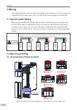
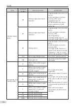
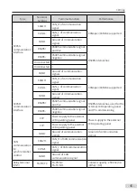
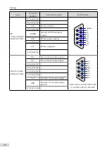
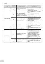
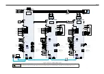
Figure 3-2
Power terminal arrangement and size of the drive unit (dual-axis)
Table 3-1
Descriptions of power terminals of the drive unit
Terminal Symbol
Terminal Function
P(+), (-)
DC bus terminals
U, V, W
U1, V1, W1
U2, V2, W2
Three-phase AC output terminals
PE terminal
3.2.2 Recommended Cable of Power Terminals
Table 3-2
Recommended cable dimensions and tightening torque
Drive Unit Model
Output Terminal (U, V, W)
Ground Terminal (PE)
Output
Cable
(mm
2
)
Screw
Spec.
Tightening
Torque
(N·m)
Ground
Cable
(mm
2
)
Screw
Spec.
Tightening
Torque
(N·m)
MD810-50M4T1.5GXXX
0.75
M5
2.8
0.75
M5
2.8
MD810-50M4T2.2GXXX
0.75
M5
2.8
0.75
M5
2.8
MD810-50M4T3.7GXXX
1.0
M5
2.8
1.0
M5
2.8
MD810-50M4T5.5GXXX
1.5
M5
2.8
1.5
M5
2.8

