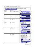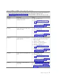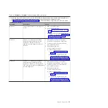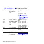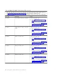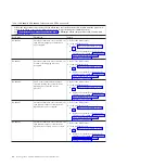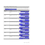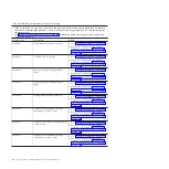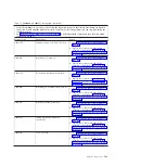
Table 14. BA000010 to BA400002 Partition firmware SRCs (continued)
v
Follow the suggested actions in the order in which they are listed in the Action column until the problem is
solved. If an action solves the problem, then you can stop performing the remaining actions.
v
See Chapter 3, “Parts listing, Type 7998,” on page 235 to determine which components are CRUs and which
components are FRUs.
Error code
Description
Action
BA400001
Informational message: DMA trace
buffer full.
1.
Reboot the blade server.
2.
If the problem persists:
a.
Go to “Checkout procedure” on page
186.
b.
Replace the system-board and chassis
assembly, as described in “Replacing the
Tier 2 system-board and chassis
assembly” on page 274.
BA400002
Informational message: DMA map-out
size mismatch.
1.
Reboot the blade server.
2.
If the problem persists:
a.
Go to “Checkout procedure” on page
186.
b.
Replace the system-board and chassis
assembly, as described in “Replacing the
Tier 2 system-board and chassis
assembly” on page 274.
POST progress codes (checkpoints)
When you turn on the blade server, the power-on self-test (POST) performs a series
of tests to check the operation of the blade server components. Use the
management module to view progress codes that offer information about the
stages involved in powering on and performing an initial program load (IPL).
Progress codes do not indicate an error, although in some cases, the blade server
can pause indefinitely (hang). Progress codes for blade servers are 9-word, 8-digit
hexadecimal numbers that start with C and D.
Checkpoints are generated by various components. The baseboard management
controller (BMC) service processor and the partitioning firmware are key
contributors. The service processor provides additional isolation procedure codes
for troubleshooting.
A checkpoint might have an associated location code as part of the message. The
location code provides information that identifies the failing component when
there is a hang condition.
Notes:
1.
For checkpoints with no associated location code, see “Light path diagnostics”
on page 218 to identify the failing component when there is a hang condition.
2.
For checkpoints with location codes, see “Location codes” on page 14 to
identify the failing component when there is a hang condition.
3.
For eight-digit codes not listed here, see “Checkout procedure” on page 186 for
information.
88
JS12 Type 7998: Problem Determination and Service Guide
Summary of Contents for BladeCenter JS12
Page 1: ...BladeCenter JS12 Type 7998 Problem Determination and Service Guide...
Page 2: ......
Page 3: ...BladeCenter JS12 Type 7998 Problem Determination and Service Guide...
Page 14: ...xii JS12 Type 7998 Problem Determination and Service Guide...
Page 248: ...234 JS12 Type 7998 Problem Determination and Service Guide...
Page 252: ...238 JS12 Type 7998 Problem Determination and Service Guide...
Page 290: ...276 JS12 Type 7998 Problem Determination and Service Guide...
Page 298: ...284 JS12 Type 7998 Problem Determination and Service Guide...
Page 302: ...288 JS12 Type 7998 Problem Determination and Service Guide...
Page 312: ...298 JS12 Type 7998 Problem Determination and Service Guide...
Page 317: ......
Page 318: ...Part Number 60Y1568 Printed in USA 1P P N 60Y1568...


