D1xx3y01 to D1xx3yF2 Service processor dump codes:
These D1xx3yxx service processor dump codes use the format:
D1
xx
3
yzz
, where
xx
indicates the cage or node ID that the dump component is processing,
y
increments
from
0
to
F
to indicate that the system is not hung, and
zz
indicates the command
being processed.
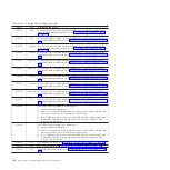
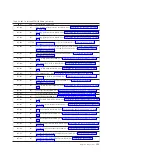
Table 21 lists the progress codes that might be displayed during the power-on
self-test (POST), along with suggested actions to take if the system hangs on the
progress code. Only when you experience a hang condition should you take any of
the actions described for a progress code.
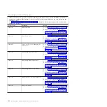
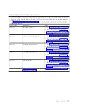
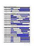
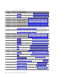
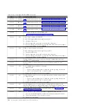
Table 21. D1xx3y01 to D1xx3yF2 checkpoints
v
If the system hangs on a progress code, follow the suggested actions in the order in which they are listed in
the Action column until the problem is solved. If an action solves the problem, you can stop performing the
remaining actions.
v
See Chapter 3, “Parts listing, Type 7998,” on page 235 to determine which components are CRUs and which
components are FRUs.
Progress code
Description
(Command Being Processed)
Action
D1xx3y01
Get SCOM
1.
Go to “Checkout procedure” on page 186.
2.
Replace the system-board and chassis
assembly, as described in “Replacing the
Tier 2 system-board and chassis assembly”
on page 274.
D1xx3y02
Get scan ring
1.
Go to “Checkout procedure” on page 186.
2.
Replace the system-board and chassis
assembly, as described in “Replacing the
Tier 2 system-board and chassis assembly”
on page 274.
D1xx3y03
Get array values
1.
Go to “Checkout procedure” on page 186.
2.
Replace the system-board and chassis
assembly, as described in “Replacing the
Tier 2 system-board and chassis assembly”
on page 274.
D1xx3y04
Stop the clocks
1.
Go to “Checkout procedure” on page 186.
2.
Replace the system-board and chassis
assembly, as described in “Replacing the
Tier 2 system-board and chassis assembly”
on page 274.
D1xx3y05
Flush the cache
1.
Go to “Checkout procedure” on page 186.
2.
Replace the system-board and chassis
assembly, as described in “Replacing the
Tier 2 system-board and chassis assembly”
on page 274.
D1xx3y06
Get CFAM
1.
Go to “Checkout procedure” on page 186.
2.
Replace the system-board and chassis
assembly, as described in “Replacing the
Tier 2 system-board and chassis assembly”
on page 274.
138
JS12 Type 7998: Problem Determination and Service Guide
Summary of Contents for BladeCenter JS12
Page 1: ...BladeCenter JS12 Type 7998 Problem Determination and Service Guide...
Page 2: ......
Page 3: ...BladeCenter JS12 Type 7998 Problem Determination and Service Guide...
Page 14: ...xii JS12 Type 7998 Problem Determination and Service Guide...
Page 248: ...234 JS12 Type 7998 Problem Determination and Service Guide...
Page 252: ...238 JS12 Type 7998 Problem Determination and Service Guide...
Page 290: ...276 JS12 Type 7998 Problem Determination and Service Guide...
Page 298: ...284 JS12 Type 7998 Problem Determination and Service Guide...
Page 302: ...288 JS12 Type 7998 Problem Determination and Service Guide...
Page 312: ...298 JS12 Type 7998 Problem Determination and Service Guide...
Page 317: ......
Page 318: ...Part Number 60Y1568 Printed in USA 1P P N 60Y1568...


