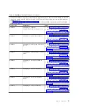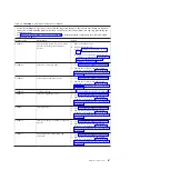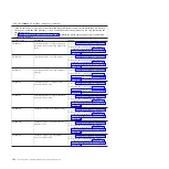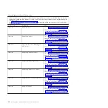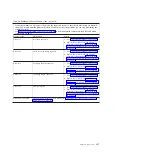
Table 19. CA000000 to CA2799FF checkpoints (continued)
v
If the system hangs on a progress code, follow the suggested actions in the order in which they are listed in
the Action column until the problem is solved. If an action solves the problem, you can stop performing the
remaining actions.
v
See Chapter 3, “Parts listing, Type 7998,” on page 235 to determine which components are CRUs and which
components are FRUs.
Progress code
Description
Action
CA00E1F2
Power on password prompt
1.
Go to “Checkout procedure” on page 186.
2.
Replace the system-board and chassis
assembly, as described in “Replacing the
Tier 2 system-board and chassis assembly”
on page 274.
CA00E1F3
Privileged-access password prompt
1.
Go to “Checkout procedure” on page 186.
2.
Replace the system-board and chassis
assembly, as described in “Replacing the
Tier 2 system-board and chassis assembly”
on page 274.
CA00E1F4
End self-test sequence on one or more
boot devices; begin system management
services
1.
Go to “Checkout procedure” on page 186.
2.
Replace the system-board and chassis
assembly, as described in “Replacing the
Tier 2 system-board and chassis assembly”
on page 274.
CA00E1F5
Build boot device list
1.
Go to “Checkout procedure” on page 186.
2.
Replace the system-board and chassis
assembly, as described in “Replacing the
Tier 2 system-board and chassis assembly”
on page 274.
CA00E1F6
Determine boot device sequence
1.
Go to “Checkout procedure” on page 186.
2.
Replace the system-board and chassis
assembly, as described in “Replacing the
Tier 2 system-board and chassis assembly”
on page 274.
CA00E1F7
No boot image located
Go to “Boot problem resolution” on page 193.
CA00E1F8
Build boot device list for SCSI adapters.
(The location code of the SCSI adapter
being scanned is also displayed.)
1.
Go to “Checkout procedure” on page 186.
2.
Replace the system-board and chassis
assembly, as described in “Replacing the
Tier 2 system-board and chassis assembly”
on page 274.
CA00E1F9
Build boot device list for fibre-channel
adapters. (The location code of the SAN
adapter being scanned is also
displayed.)
1.
Go to “Checkout procedure” on page 186.
2.
Replace the system-board and chassis
assembly, as described in “Replacing the
Tier 2 system-board and chassis assembly”
on page 274.
CA00E1FA
Building device list for SCSI adapters.
(The device ID and device LUN of the
device being scanned is also displayed.)
1.
Go to “Checkout procedure” on page 186.
2.
Replace the system-board and chassis
assembly, as described in “Replacing the
Tier 2 system-board and chassis assembly”
on page 274.
Chapter 2. Diagnostics
125
Summary of Contents for BladeCenter JS12
Page 1: ...BladeCenter JS12 Type 7998 Problem Determination and Service Guide...
Page 2: ......
Page 3: ...BladeCenter JS12 Type 7998 Problem Determination and Service Guide...
Page 14: ...xii JS12 Type 7998 Problem Determination and Service Guide...
Page 248: ...234 JS12 Type 7998 Problem Determination and Service Guide...
Page 252: ...238 JS12 Type 7998 Problem Determination and Service Guide...
Page 290: ...276 JS12 Type 7998 Problem Determination and Service Guide...
Page 298: ...284 JS12 Type 7998 Problem Determination and Service Guide...
Page 302: ...288 JS12 Type 7998 Problem Determination and Service Guide...
Page 312: ...298 JS12 Type 7998 Problem Determination and Service Guide...
Page 317: ......
Page 318: ...Part Number 60Y1568 Printed in USA 1P P N 60Y1568...

