2.
Read “Safety” on page v and the “Installation guidelines” on page 239.
3.
If you have not done so already, install any optional devices that you want,
such as a SAS drive or memory modules.
4.
Select the bay for the blade server.
v
See the online information or the
Installation and User’s Guide
that comes
with your BladeCenter unit to verify that the bay you choose is powered.
v
Ensure proper cooling, performance, and system reliability by installing a
blade server, expansion unit, or blade filler in each blade bay.
v
Reinstall a blade server in the same blade bay to preserve some
configuration information and update options that are established by blade
bay. Reinstalling into a different blade bay can have unintended
consequences, which might include reconfiguring the blade server.
5.
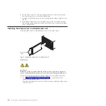
Verify that the release handles on the blade server are in the open position
(perpendicular to the blade server).
6.
If you installed a filler blade or another blade server in the bay from which
you removed the blade server, remove it from the bay.
7.
Slide the blade server into the blade bay from which you removed it until the
blade server stops.
The spring-loaded doors farther back in the bay that cover the bay opening
move out of the way as you insert the blade server.
8.
Push the release handles on the front of the blade server to close and lock
them.
The discovery and initialization process can take up to three minutes to
complete. The discovery and initialization process is complete when the green
LED stops flashing rapidly and begins to flash slowly. At this point, you can
power on the blade server.
9.
Turn on the blade server. See “Turning on the blade server” on page 7.
10.
Verify that the power-on LED on the blade server control panel is lit
continuously. The continuous light indicates that the blade server is receiving
power and is turned on.
11.
Optional: Write identifying information on one of the user labels that come
with the blade servers and place the label on the BladeCenter unit bezel.
Important:
Do not place the label on the blade server or in any way block the
ventilation holes on the blade server. See the online information or the
documentation that comes with your BladeCenter unit for information about
label placement.
12.
Use the SMS Utility program to configure the blade server. See “Using the
SMS utility” on page 279.
13.
Also use the management module to configure the blade server. See the
documentation for the management module to understand the functions that
the management module provides.
Chapter 4. Removing and replacing blade server components
243
Summary of Contents for BladeCenter JS12
Page 1: ...BladeCenter JS12 Type 7998 Problem Determination and Service Guide...
Page 2: ......
Page 3: ...BladeCenter JS12 Type 7998 Problem Determination and Service Guide...
Page 14: ...xii JS12 Type 7998 Problem Determination and Service Guide...
Page 248: ...234 JS12 Type 7998 Problem Determination and Service Guide...
Page 252: ...238 JS12 Type 7998 Problem Determination and Service Guide...
Page 290: ...276 JS12 Type 7998 Problem Determination and Service Guide...
Page 298: ...284 JS12 Type 7998 Problem Determination and Service Guide...
Page 302: ...288 JS12 Type 7998 Problem Determination and Service Guide...
Page 312: ...298 JS12 Type 7998 Problem Determination and Service Guide...
Page 317: ......
Page 318: ...Part Number 60Y1568 Printed in USA 1P P N 60Y1568...


