SRC formats
SRCs are strings of either six or eight alphanumeric characters. The first four
characters designate the reference code type and the second four characters
designate the unit reference code (URC).
The first character indicates the type of error. In a few cases, the first two
characters indicate the type of error:
v
1xxxxxxx - System power control network (SPCN) error
v
6xxxxxxx - Virtual optical device error
v
A1xxxxxx - Attention required (Service processor)
v
AAxxxxxx - Attention required (Partition firmware)
v
B1xxxxxx - Service processor error, such as a boot problem
v
BAxxxxxx - Partition firmware error
v
Cxxxxxxx - Checkpoint (must hang to indicate an error)
v
Dxxxxxxx - Dump checkpoint (must hang to indicate an error)
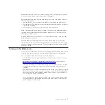
To find a description of a SRC that is not listed in this JS12 blade server
documentation, refer to the POWER6 Reference Code Lookup page at
https://www-01.ibm.com/servers/resourcelink/lib03030.nsf/pages/eClipzML/
$file/refCode.html.
1xxxyyyy SRCs
The 1xxxyyyy system reference codes are system power control network (SPCN)
reference codes.
Look for the rightmost 4 characters (
yyyy
in 1xxx
yyyy
) in the error code; this is the
reference code. Find the reference code in Table 5.
Perform all actions before exchanging failing items.
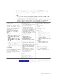
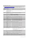
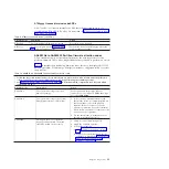
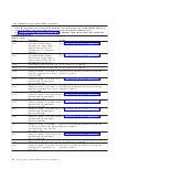
Table 5. 1xxxyyyy SRCs
v
Follow the suggested actions in the order in which they are listed in the Action column until the problem is
solved. If an action solves the problem, then you can stop performing the remaining actions.
v
See Chapter 3, “Parts listing, Type 7998,” on page 235 to determine which components are CRUs and which
components are FRUs.
1xxxyyyy
Error Codes
Description
Action
00AC
Informational message: AC
loss was reported
No action is required.
00AD
Informational message: A
service processor reset caused
the blade server to power off
No action is required.
1F02
Informational message: The
trace logs reached 1K of data.
No action is required.
2600
pGood master fault
1.
Go to “Checkout procedure” on page 186.
2.
Replace the system-board and chassis assembly, as described in
“Replacing the Tier 2 system-board and chassis assembly” on
page 274.
Chapter 2. Diagnostics
17
Summary of Contents for BladeCenter JS12
Page 1: ...BladeCenter JS12 Type 7998 Problem Determination and Service Guide...
Page 2: ......
Page 3: ...BladeCenter JS12 Type 7998 Problem Determination and Service Guide...
Page 14: ...xii JS12 Type 7998 Problem Determination and Service Guide...
Page 248: ...234 JS12 Type 7998 Problem Determination and Service Guide...
Page 252: ...238 JS12 Type 7998 Problem Determination and Service Guide...
Page 290: ...276 JS12 Type 7998 Problem Determination and Service Guide...
Page 298: ...284 JS12 Type 7998 Problem Determination and Service Guide...
Page 302: ...288 JS12 Type 7998 Problem Determination and Service Guide...
Page 312: ...298 JS12 Type 7998 Problem Determination and Service Guide...
Page 317: ......
Page 318: ...Part Number 60Y1568 Printed in USA 1P P N 60Y1568...

