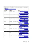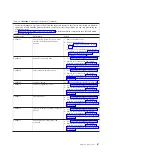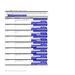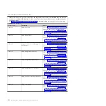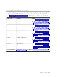
Table 19. CA000000 to CA2799FF checkpoints (continued)
v
If the system hangs on a progress code, follow the suggested actions in the order in which they are listed in
the Action column until the problem is solved. If an action solves the problem, you can stop performing the
remaining actions.
v
See Chapter 3, “Parts listing, Type 7998,” on page 235 to determine which components are CRUs and which
components are FRUs.
Progress code
Description
Action
CA00E1D0
Create PCI SCSI node
1.
Go to “Checkout procedure” on page 186.
2.
Replace the system-board and chassis
assembly, as described in “Replacing the
Tier 2 system-board and chassis assembly”
on page 274.
CA00E1D3
Create SCSI block device node (SD)
1.
Go to “Checkout procedure” on page 186.
2.
Replace the system-board and chassis
assembly, as described in “Replacing the
Tier 2 system-board and chassis assembly”
on page 274.
CA00E1D4
Create SCSI byte device node (ST)
1.
Go to “Checkout procedure” on page 186.
2.
Replace the system-board and chassis
assembly, as described in “Replacing the
Tier 2 system-board and chassis assembly”
on page 274.
CA00E1DC
Dynamic console selection
1.
Go to “Checkout procedure” on page 186.
2.
Replace the system-board and chassis
assembly, as described in “Replacing the
Tier 2 system-board and chassis assembly”
on page 274.
CA00E1DD
A graphics adapter has been selected as
the firmware console, but the USB
keyboard is not attached.
1.
Verify that there is a USB keyboard
attached to a USB port that is assigned to
the partition.
2.
If the problem persists:
a.
Go to “Checkout procedure” on page
186.
b.
Replace the system-board and chassis
assembly, as described in “Replacing the
Tier 2 system-board and chassis
assembly” on page 274.
CA00E1F0
Start out-of-box experience
1.
Go to “Checkout procedure” on page 186.
2.
Replace the system-board and chassis
assembly, as described in “Replacing the
Tier 2 system-board and chassis assembly”
on page 274.
CA00E1F1
Start self test sequence on one or more
devices
1.
Go to “Checkout procedure” on page 186.
2.
Replace the system-board and chassis
assembly, as described in “Replacing the
Tier 2 system-board and chassis assembly”
on page 274.
124
JS12 Type 7998: Problem Determination and Service Guide
Summary of Contents for BladeCenter JS12
Page 1: ...BladeCenter JS12 Type 7998 Problem Determination and Service Guide...
Page 2: ......
Page 3: ...BladeCenter JS12 Type 7998 Problem Determination and Service Guide...
Page 14: ...xii JS12 Type 7998 Problem Determination and Service Guide...
Page 248: ...234 JS12 Type 7998 Problem Determination and Service Guide...
Page 252: ...238 JS12 Type 7998 Problem Determination and Service Guide...
Page 290: ...276 JS12 Type 7998 Problem Determination and Service Guide...
Page 298: ...284 JS12 Type 7998 Problem Determination and Service Guide...
Page 302: ...288 JS12 Type 7998 Problem Determination and Service Guide...
Page 312: ...298 JS12 Type 7998 Problem Determination and Service Guide...
Page 317: ......
Page 318: ...Part Number 60Y1568 Printed in USA 1P P N 60Y1568...


