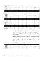
Table 6. System memory configuration for mirrored channel mode
(2 microprocessors)
Installed
memory
DIMM socket
1
2
3
4
5
6
7
8
9
10
11
12
4 DIMMs
X
X
X
X
6 DIMMs
X
X
X
X
X
X
8 DIMMs
X
X
X
X
X
X
X
X
v
Spare channel mode:
In spare channel mode, channel 2 is the spare of the active
channels 0 and 1. The spare channel is not available as active memory. The
maximum memory available (with 16 GB DIMMs) is 64 GB in a single CPU
system and 128 GB in a dual CPU system. All three channels must have
identical population with regards to size and organization. DIMMs within a
channel do not have to be identical. The population ordering for spare channel
mode is shown in the table below.
Note:
Spare channel mode is only supported if the blade server has an Intel
Xeon 5600 series microprocessor. Use the Setup utility to view the system
summary and verify the type of microprocessor installed in your blade server
(see “Using the Setup utility” on page 21).
The following table shows the order that memory DIMMs are installed to use
spare channel mode.
Table 7. System memory configuration for spare channel mode
(1 microprocessor)
Installed
memory
DIMM socket
1
2
3
4
5
6
7
8
9
10
11
12
3 DIMMs
X
X
X
6 DIMMs
X
X
X
X
X
X
Table 8. System memory configuration for spare channel mode
(2 microprocessors)
Installed
memory
DIMM socket
1
2
3
4
5
6
7
8
9
10
11
12
6 DIMMs
X
X
X
X
X
X
9 DIMMs
X
X
X
X
X
X
X
X
X
12 DIMMs
X
X
X
X
X
X
X
X
X
X
X
X
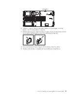
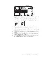
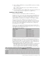
To install a DIMM, complete the following steps:
1.
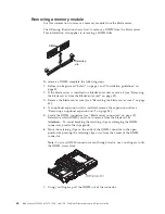
Locate the DIMM connectors (see “Blade server connectors” on page 15).
Determine which DIMM connector you will be installing memory into.
2.
If a DIMM filler or another memory module is already installed in the DIMM
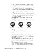
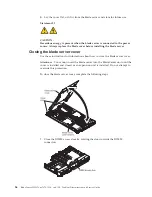
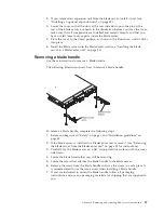
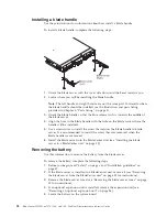
connector, remove it (see “Removing a memory module” on page 64).
Note:
A DIMM or DIMM filler must occupy each DIMM socket before the
blade server is turned on.
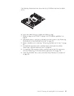
3.
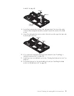
If you are installing a DIMM in DIMM connector seven through twelve, use
your fingers to lift the DIMM access door.
Chapter 5. Removing and replacing blade server components
67
Summary of Contents for 7870B4U
Page 1: ...BladeCenter HS22 Type 7870 1936 and 1911 Problem Determination and Service Guide...
Page 2: ......
Page 3: ...BladeCenter HS22 Type 7870 1936 and 1911 Problem Determination and Service Guide...
Page 14: ...xii BladeCenter HS22 Type 7870 1936 and 1911 Problem Determination and Service Guide...
Page 20: ...6 BladeCenter HS22 Type 7870 1936 and 1911 Problem Determination and Service Guide...
Page 34: ...20 BladeCenter HS22 Type 7870 1936 and 1911 Problem Determination and Service Guide...
Page 248: ...234 BladeCenter HS22 Type 7870 1936 and 1911 Problem Determination and Service Guide...
Page 252: ...238 BladeCenter HS22 Type 7870 1936 and 1911 Problem Determination and Service Guide...
Page 260: ...246 BladeCenter HS22 Type 7870 1936 and 1911 Problem Determination and Service Guide...
Page 266: ...252 BladeCenter HS22 Type 7870 1936 and 1911 Problem Determination and Service Guide...
Page 267: ......
Page 268: ...Part Number 90Y5614 Printed in USA 1P P N 90Y5614...


