v
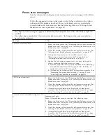
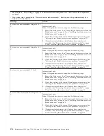
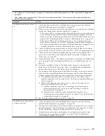
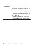
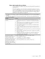
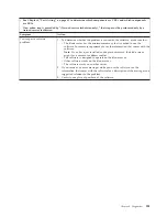
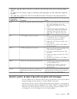
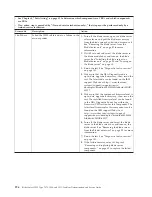
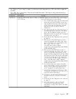
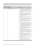
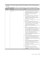
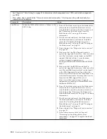
Follow the suggested actions in the order in which they are listed in the Action column until the problem is
solved.
v
See Chapter 4, “Parts listing,” on page 41 to determine which components are CRUs and which components
are FRUs.
v
If an action step is preceded by “(Trained service technician only),” that step must be performed only by a
trained service technician.
Lit light path
diagnostics LED
Description
Action
SYS BRD (System
board error)
The system board has failed
(Trained service technician only) Replace the
system-board assembly - See “Removing the
system-board assembly” on page 97 and
“Installing the system-board assembly” on
page 98.
TEMP (Over
temperature error)
The system temperature has exceeded a
threshold level.
1.
Check the function of the shared
BladeCenter unit resources. See “Solving
shared BladeCenter resource problems” on
page 227.
2.
Make sure the air vents are not blocked
and that all blade bays in the BladeCenter
unit have a blade server or a blade filler
installed.
3.
Make sure that the room temperature is
not too high. See “Features and
specifications” on page 9 for temperature
information.
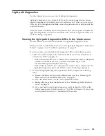
Viewing the light path diagnostics LEDs in the BladeCenter
GPU expansion unit
When an error is indicated by the fault LED on the front of the BladeCenter GPU
expansion (BGE) unit, these LEDs inside the expansion unit can be lit to help
identify the source of the error. The fault LED on the blade server on which the
expansion unit is installed is also lit. If the blade server supports transfer of error
and LED information, fault-related information will be shown by the BladeCenter
advanced management module (see the
BladeCenter Advanced Management Module
User's Guide
for additional information).
Before you work inside the expansion unit to view light path diagnostics LEDs,
read “Safety” on page v and “Installation guidelines” on page 49.
To view the light path diagnostics LEDs in the expansion unit:
1.
Remove the combined blade server and expansion units from the BladeCenter
unit (see “Removing the blade server from the BladeCenter unit” on page 52).
2.
Place the expansion unit on a flat, static-protective surface.
3.
Remove the expansion unit cover and other expansion blades, if applicable, to
expose the expansion unit that has the lit fault LED. See “Removing the blade
server cover” on page 55.
4.
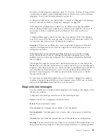
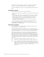
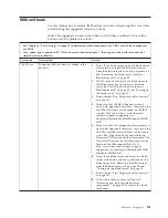
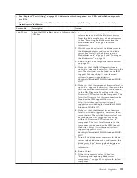
Press and hold the light path diagnostics switch for a maximum of 25 seconds.
The light path diagnostics (LP) LED will be lit (green) to indicate that there is
enough power present to light the error LEDs, and LEDs indicating additional
failure information also will be lit.
Chapter 6. Diagnostics
187
Summary of Contents for 7870B4U
Page 1: ...BladeCenter HS22 Type 7870 1936 and 1911 Problem Determination and Service Guide...
Page 2: ......
Page 3: ...BladeCenter HS22 Type 7870 1936 and 1911 Problem Determination and Service Guide...
Page 14: ...xii BladeCenter HS22 Type 7870 1936 and 1911 Problem Determination and Service Guide...
Page 20: ...6 BladeCenter HS22 Type 7870 1936 and 1911 Problem Determination and Service Guide...
Page 34: ...20 BladeCenter HS22 Type 7870 1936 and 1911 Problem Determination and Service Guide...
Page 248: ...234 BladeCenter HS22 Type 7870 1936 and 1911 Problem Determination and Service Guide...
Page 252: ...238 BladeCenter HS22 Type 7870 1936 and 1911 Problem Determination and Service Guide...
Page 260: ...246 BladeCenter HS22 Type 7870 1936 and 1911 Problem Determination and Service Guide...
Page 266: ...252 BladeCenter HS22 Type 7870 1936 and 1911 Problem Determination and Service Guide...
Page 267: ......
Page 268: ...Part Number 90Y5614 Printed in USA 1P P N 90Y5614...

