background image

v

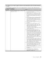
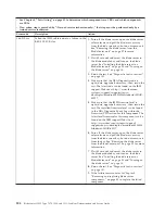
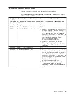
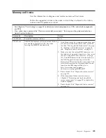
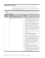
See Chapter 4, “Parts listing,” on page 41 to determine which components are CRUs and which components
are FRUs.

v

If an action step is preceded by “(Trained service technician only),” that step must be performed only by a
trained service technician.

Error code

Description

Action

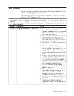
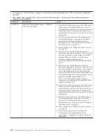
089-802-xxx

Aborted due a system resource availability
error.

1.

If the blade server has stopped responding, turn
off and restart the blade server. See “Turning off
the blade server” on page 14 and “Turning on
the blade server” on page 14.

2.

Make sure that the DSA Diagnostic code is
up-to-date, upgrade if necessary; then, rerun the
test. The latest code can be found on the IBM
support Web site at http://www.ibm.com/
support/docview.wss?uid=psg1SERV-DSA.

3.

Make sure that the system firmware level is
up-to-date, upgrade if necessary; then, rerun the
test. The installed firmware level can be found
in the DSA Diagnostic Event Log within the
Firmware/VPD section for this component. The
latest level firmware for this component can be
found on the IBM support Web site at
http://www.ibm.com/systems/support/
supportsite.wss/docdisplay?brandind=5000008
&lndocid=MIGR-63017.

4.

If the blade server has stopped responding, turn
off and restart the blade server; then, rerun the
test. See “Turning off the blade server” on page
14 and “Turning on the blade server” on page
14.

5.

(Trained service technician only) If the
component failure remains, refer to Chapter 5,
“Removing and replacing blade server
components,” on page 49 to replace the failed
component.

Chapter 6. Diagnostics

207

Summary of Contents for 7870B4U

Page 1: ...BladeCenter HS22 Type 7870 1936 and 1911 Problem Determination and Service Guide...

Page 2: ......

Page 3: ...BladeCenter HS22 Type 7870 1936 and 1911 Problem Determination and Service Guide...

Page 4: ...Notices and User Guide Warranty Information documents on the IBM Documentation CD The most recent version of this document is available at http www ibm com systems support Fourteenth Edition July 201...

Page 5: ...dling static sensitive devices 50 Returning a device or component 51 Removing the blade server from the BladeCenter unit 52 Installing the blade server in a BladeCenter unit 53 Removing and replacing...

Page 6: ...shared BladeCenter resource problems 227 Keyboard or mouse problems 228 Media tray problems 228 Network connection problems 229 Power problems 230 Video problems 231 Solving undetermined problems 232...

Page 7: ...krifterne f r du installerer dette produkt Lees voordat u dit product installeert eerst de veiligheidsvoorschriften Ennen kuin asennat t m n tuotteen lue turvaohjeet kohdasta Safety Information Avant...

Page 8: ...with a number This number is used to cross reference an English language caution or danger statement with translated versions of the caution or danger statement in the Safety Information document For...

Page 9: ...and disconnect cables as described in the following table when installing moving or opening covers on this product or attached devices To Connect To Disconnect 1 Turn everything OFF 2 First attach al...

Page 10: ...ose specified herein might result in hazardous radiation exposure DANGER Some laser products contain an embedded Class 3A or Class 3B laser diode Note the following Laser radiation when open Do not st...

Page 11: ...oltage current and energy levels are present inside any component that has this label attached There are no serviceable parts inside these components If you suspect a problem with one of these parts c...

Page 12: ...talling the blade Statement 32 CAUTION To avoid personal injury before lifting the unit remove all the blades power supplies and removable modules to reduce the weight 108 kg 237 lbs 2X 6X 4X 4X 43 2...

Page 13: ...ers and optional devices starting from the bottom of the rack cabinet v Always install the heaviest devices in the bottom of the rack cabinet United Kingdom telecommunications safety requirement Notic...

Page 14: ...xii BladeCenter HS22 Type 7870 1936 and 1911 Problem Determination and Service Guide...

Page 15: ...ice drivers v Firmware v Hardware components v Software If possible return the blade server to the condition it was in before the problem occurred 2 Collect data Thorough data collection is necessary...

Page 16: ...BladeCenter Tools Center 3 Click Tools reference Error reporting and analysis tools IBM Dynamic System Analysis c Collect BladeCenter unit data Data about the BladeCenter unit is available through the...

Page 17: ...adable files for the blade server You can install code updates that are packaged as an IBM UpdateXpress System Pack or UpdateXpress CD image An UpdateXpress System Pack contains an integration tested...

Page 18: ...hanges are made periodically to the IBM Web site The actual procedure might vary slightly from what is described in this document a Go to http www ibm com systems support b Under Product support click...

Page 19: ...d the problem remains the problem might not have been previously identified by IBM After you have verified that all code is at the latest level all hardware and software configurations are valid and n...

Page 20: ...6 BladeCenter HS22 Type 7870 1936 and 1911 Problem Determination and Service Guide...

Page 21: ...entation Use this information to identify and locate related blade server documentation This Problem Determination and Service Guide document is in Portable Document Format PDF on the IBM Documentatio...

Page 22: ...s described in this document 1 Go to http www ibm com systems support 2 Under Product support click BladeCenter 3 Under Popular links click Publications lookup 4 From the Product family menu select Bl...

Page 23: ...r Notes 1 Power cooling removable media drives external ports and advanced system management are provided by the BladeCenter unit 2 The operating system in the blade server must provide USB support fo...

Page 24: ...t Blade server off 10 C to 43 C 50 F to 109 4 F Altitude 914 4 m to 2133 6 m 3000 ft to 7000 ft Blade server shipping 40 C to 60 C 40 F to 140 F v Humidity Blade server on 8 to 80 Blade server off 8 t...

Page 25: ...s power supplied and is ready to be turned on v Lit continuously The blade server has power and is turned on Activity LED When this green LED is lit it indicates that there is activity on the external...

Page 26: ...ing a keyboard that is directly attached to the Advanced Management Module you can press keyboard keys in the following sequence to switch KVM control between blade servers instead of using the KVM se...

Page 27: ...ade server Note The operating system in the blade server must provide USB support for the blade server to recognize and use the removable media drives The following illustration identifies the informa...

Page 28: ...e management module the operating system supports the Wake on LAN feature and the Wake on LAN feature has not been disabled through the management module the Wake on LAN feature can turn on the blade...

Page 29: ...es on the system board The illustrations in this document might differ slightly from your hardware Blade server connectors Use this information to locate blade server system board components and conne...

Page 30: ...a functioning system SW1 2 Trusted Platform Module TPM physical presence The default position is off Turning this switch to the on position indicates a physical presence to the TPM SW1 3 ICH9 RTC res...

Page 31: ...ate The default position is off For trained service technician only SW1 7 Wake on LAN WOL disable The default position is off Turning this switch to the on position disables WOL SW1 8 Force H8 update...

Page 32: ...D NMI System board error LED NMI error LED Over Temperature LED Microprocessor mismatch LED Light Path diagnostic LED Light Path diagnostic switch The following illustration shows the LEDs on the syst...

Page 33: ...is corrected If an error occurs in the expansion blade the fault LED on the blade device on which the expansion blade is installed is also lit Additional information about the error is provided by the...

Page 34: ...20 BladeCenter HS22 Type 7870 1936 and 1911 Problem Determination and Service Guide...

Page 35: ...bout obtaining and using this CD see Using the ServerGuide Setup and Installation CD on page 31 v Preboot Execution Environment PXE boot agent utility program The PXE boot agent utility program is par...

Page 36: ...he microprocessors machine type and model of the server the serial number the system UUID and the amount of installed memory When you make configuration changes through other options in the Setup util...

Page 37: ...port the IMM MAC address the current IMM IP address and host name define the static IMM IP address subnet mask and gateway address specify whether to use the static IP address or have DHCP assign the...

Page 38: ...ter 6 Diagnostics on page 101 for instructions on running the diagnostic programs Important If the system error LED on the front of the server is lit but there are no other error indications clear the...

Page 39: ...remove it You must replace the system board Using the Boot Menu program Use the Boot Menu program to temporarily redefine the first startup device without changing settings in the Setup utility The Bo...

Page 40: ...he Integrated Management Module IMM Select one of the following methods to access the Integrated Management Module IMM to set the UUID v Online from the target system LAN or keyboard console style KCS...

Page 41: ...uid_value user user_id password password Example that does use the userid and password default values asu set SYSTEM_PROD_DATA SysInfoUUID uuid_value v Online KCS access unauthenticated and user restr...

Page 42: ...ia using the applications available through the Tools Center Web site at http publib boulder ibm com infocenter toolsctr v1r0 index jsp From the left pane click IBM System x and BladeCenter Tools Cent...

Page 43: ...Windows and Linux based tool kits are also available to build a bootable media These tool kits provide an alternate method to creating a Windows Professional Edition or Master Control Program MCP base...

Page 44: ...user_id password imm_password asu set SYSTEM_PROD_DATA SYsEncloseAssetTag asset_tag user imm_user_id password imm_password Examples that do use the userid and password default values asu set SYSTEM_PR...

Page 45: ...the userid and password default values asu set SYSTEM_PROD_DATA SysInfoProdName m t_model host imm_ip asu set SYSTEM_PROD_DATA SysInfoSerialNum s n host imm_ip asu set SYSTEM_PROD_DATA SysEncloseAsset...

Page 46: ...ive In addition to the ServerGuide Setup and Installation CD you must have the operating system CD to install the operating system The ServerGuide program has the following features v Sets system date...

Page 47: ...section describes a typical ServerGuide operating system installation Note Features and functions can vary slightly with different versions of the ServerGuide program 1 After you have completed the se...

Page 48: ...ent utility program complete the following steps 1 Turn on the server see Turning on the blade server on page 14 2 When the Broadcom NetXtreme Boot Agent vX X X prompt is displayed press Ctrl S You ha...

Page 49: ...controller provides a 1000 Mbps full duplex interface for connecting to one of the Ethernet compatible I O modules in I O module bays 1 and 2 which enables simultaneous transmission and reception of d...

Page 50: ...rogram to configure the storage drives and the SAS controller To start the LSI Logic Configuration Utility see Using the LSI Logic Configuration Utility program Using the LSI Logic Configuration Utili...

Page 51: ...applications or both For example Open MPI attempts to use all of the available network interfaces on a server Open MPI detects the IMM LAN over USB interface and attempts to use it to communicate with...

Page 52: ...USB interface d Select the check boxes next to the blade or blades that you want to enable or disable e Click the Disable button to disable the LAN over USB interface on the selected blades Configuri...

Page 53: ...me name in WINDOWS inf For Windows 2008 Go to Computer Management then Device Manager and find the RNDIS Device Select Properties Driver Reinstall driver Point the server to the Windows inf directory...

Page 54: ...SB on specific Linux distributions see the IBM white paper Transitioning to UEFI and IMM on the IBM web site see Related documentation on page 7 for information on how to find publications for your bl...

Page 55: ...ourself or request IBM to install it at no additional charge under the type of warranty service that is designated for your server v Field replaceable unit FRU FRUs must be installed only by trained s...

Page 56: ...scription CRU part number Tier 1 CRU part number Tier 2 FRU part number 1 Cover Type 7870 46C7201 1 Cover Type 1911 68Y7425 2 Expansion card Broadcom 10 Gb 2 port Ethernet CFFh model CCx 44W4469 2 Exp...

Page 57: ...86GTps QPI 1066MHz 8MB 38W dual core option 59Y5571 4 Microprocessor Intel Xeon L5638 2 0 GHz 5 86GTps QPI 12MB 60W six core option 69Y4715 4 Microprocessor Intel Xeon E5503 2 0 GHz 4 8GTps QPI 800MH...

Page 58: ...eon X5550 2 67 GHz 6 4 GTps QPI 1333MHz 8MB 95W quad core option 46D1264 4 Microprocessor Intel Xeon X5560 2 80 GHz 6 4 GTps QPI 1333MHz 8MB 95W quad core models 1Mx 5Mx C3x ECx 46D1263 4 Microprocess...

Page 59: ...y 2 GB 1Rx8 2 Gb DDR3 RDIMM option 44T1584 6 Memory 2 GB 1Rx8 2 Gb ECC RDIMM option 46C0572 6 Memory 4 GB 1Gb 2Rx4 VLP DDR3 1333 1 35V option 46C0579 6 Memory 4 GB dual rank VLP DDR3 1333 PC3 10600 op...

Page 60: ...Solid state drive 2 5 inch SFF slim High IOPS hot swap SATA 50 GB option 43W7717 10 Blade handle right included in the miscellaneous parts kit 46D1122 11 Blade handle left included in the miscellaneo...

Page 61: ...Y8747 Alcohol Wipe Kit Taiwan Japan 41Y8748 Alcohol Wipe Kit China Malaysia 41Y8749 Alcohol Wipe Kit Austrailia UK 41Y8750 Alcohol Wipe Kit Korea 41Y8751 Alcohol Wipe Kit Other Countries 41Y8752 Alcoh...

Page 62: ...8Y9633 VMware ESXi4 0 U1 without USB module 68Y9634 VMware ESXi4 1 SW without USB module 81Y2028 VMware ESX server 3i recovery CD kit version 3 5 46D0762 VMware ESX server 3i recovery CD kit version 3...

Page 63: ...fore you begin read Safety on page v and Handling static sensitive devices on page 50 This information will help you work safely v When you install your new blade server take the opportunity to downlo...

Page 64: ...iller or a microprocessor and heat sink If the blade server has only one microprocessor it must be installed in microprocessor socket 1 v Each DIMM socket always contains a memory module or filler v E...

Page 65: ...vice If it is necessary to set down the device put it back into its static protective package Do not place the device on the blade server cover or on a metal surface v Take additional care when you ha...

Page 66: ...ions are established according to blade server bay number if you reinstall the blade server into a different bay you might have to reconfigure the blade server To remove the blade server complete the...

Page 67: ...BladeCenter unit might be different see the documentation for your BladeCenter unit for additional information To install a blade server in a BladeCenter unit complete the following steps Statement 21...

Page 68: ...erver Attention Two people are required to install a Type 1911 blade server into the bay Statement 4 for Type 1911 18 kg 39 7 lb 32 kg 70 5 lb 55 kg 121 2 lb CAUTION Use safe practices when lifting 4...

Page 69: ...RUs Use this information for removing and replacing Tier 1 CRUs Replacement of Tier 1 CRUs is your responsibility If IBM installs a Tier 1 CRU at your request you will be charged for the installation...

Page 70: ...ese instructions for information about how to close the blade server cover Attention You cannot insert the blade server into the BladeCenter unit until the cover is installed and closed or an expansio...

Page 71: ...lowing illustration shows how to remove a blade handle To remove a blade handle complete the following steps 1 Before you begin read Safety on page v and Installation guidelines on page 49 2 If the bl...

Page 72: ...blade handle to blade server It is recommended to install the screw that was removed when the blade handle was removed 6 Install the blade server into the BladeCenter unit see Installing the blade se...

Page 73: ...battery by using your finger to press the top of the battery towards the middle of the blade server and out of the battery connector 8 Use your thumb and index finger to lift the battery from the soc...

Page 74: ...by the same manufacturer The battery contains lithium and can explode if not properly used handled or disposed of Do not v Throw or immerse into water v Heat to more than 100 C 212 F v Repair or disa...

Page 75: ...ector 11 Install the optional expansion unit if you removed one from the blade server to replace the battery see Installing an optional expansion unit on page 85 for instructions 12 Install the cover...

Page 76: ...following steps 1 Before you begin read Safety on page v and Installation guidelines on page 49 2 Press the release latch orange on the storage drive to release the drive handle 3 Pull the release ha...

Page 77: ...ollowing steps 1 Identify the SAS storage bay storage bay 0 or storage bay 1 in which the hot swap storage drive will be installed see Blade server connectors on page 15 2 If a storage bay filler is i...

Page 78: ...cover on page 55 4 If an optional expansion unit is installed remove the expansion unit see Removing an optional expansion unit on page 84 5 Locate the DIMM connectors see Blade server connectors on...

Page 79: ...system using six channels Each channel contains two DIMM connectors The following table lists each channel and which DIMM connectors belong to the channel Table 2 Memory channel configuration Memory c...

Page 80: ...annel 3 are duplicated in channel 4 The effective memory available to the system is only half of that installed The maximum available memory with 16 GB DIMMs is 32 GB for a single CPU system and 64 GB...

Page 81: ...e Using the Setup utility on page 21 The following table shows the order that memory DIMMs are installed to use spare channel mode Table 7 System memory configuration for spare channel mode 1 micropro...

Page 82: ...e DIMM connector The retaining clips will lock the DIMM into the connector d Make sure that the small tabs on the retaining clips are in the notches on the DIMM If there is a gap between the DIMM and...

Page 83: ...rom the BladeCenter unit on page 52 3 Remove the blade server cover see Removing the blade server cover on page 55 4 If an optional expansion unit is installed remove the expansion unit see Removing a...

Page 84: ...t contains the USB Flash key to any unpainted metal surface on the BladeCenter unit or any unpainted metal surface on any other grounded rack component in the rack in which you are installing the USB...

Page 85: ...1 Before you begin read Safety on page v and Installation guidelines on page 49 2 If the blade server is installed in a BladeCenter unit remove it see Removing the blade server from the BladeCenter u...

Page 86: ...lation guidelines on page 49 2 If the blade server is installed in a BladeCenter unit remove it see Removing the blade server from the BladeCenter unit on page 52 for instructions 3 Carefully lay the...

Page 87: ...ade server is installed in a BladeCenter unit remove it see Removing the blade server from the BladeCenter unit on page 52 for instructions 3 Remove the blade server cover see Removing the blade serve...

Page 88: ...hpoint on the cable then pull the cable away from the backup battery 7 The backup battery is installed in DIMM connector seven To remove the backup battery complete the following steps a If you have n...

Page 89: ...n Card CIOv for IBM BladeCenter v QLogic 4 Gb Fibre Channel Expansion Card CIOv for IBM BladeCenter v SAS Connectivity Card CIOv for IBM BladeCenter v ServeRAID MR10ie CIOv Controller for IBM BladeCen...

Page 90: ...ernet Expansion Card CFFh for IBM BladeCenter To install a CFFh expansion card complete the following steps 1 Locate the blade server expansion connector see Blade server connectors on page 15 2 If a...

Page 91: ...er Review the tables in Installing a memory module on page 65 to make sure that your memory configuration will not be affected Attention Before you install a ServeRAID MR10ie controller in the blade s...

Page 92: ...the end of the cable marked EXPANSION CARD then with the blue side of the cable end facing up carefully insert the cable end into the cable connector on the ServeRAID controller 5 Orient the connecto...

Page 93: ...t over the top of the heat sink for microprocessor two 10 If you removed an optional expansion unit reinstall it see Installing an optional expansion unit on page 85 11 Install the cover onto the blad...

Page 94: ...might differ slightly from your hardware To remove the bezel assembly complete the following steps 1 Before you begin read Safety on page v and Installation guidelines on page 49 2 If the blade server...

Page 95: ...upplied to you Installing the bezel assembly Use this information to install a bezel assembly in the blade server Note 1 The following illustration shows how to install a bezel assembly in a blade ser...

Page 96: ...he system board 2 The illustrations in this document might differ slightly from your hardware To remove the control panel complete the following steps Control panel connector Control panel cable 1 Bef...

Page 97: ...onent in the rack in which you are installing the control panel for at least two seconds then remove the USB module from its package 3 Orient the control panel so the cable aligns with the control pan...

Page 98: ...e up 4 Remove the blade server cover if one is installed see Removing the blade server cover on page 55 for instructions 5 Remove the expansion unit a If the expansion unit has an extraction device us...

Page 99: ...n connector on the blade server system board or the expansion unit and remove the cover if one is installed see Blade server connectors on page 15 2 Touch the static protective package that contains t...

Page 100: ...pansion unit 2 The illustrations in this document might differ slightly from your hardware To remove a GPU adapter from the BladeCenter GPU expansion unit complete the following steps 1 Before you beg...

Page 101: ...tton d Press in and hold the tray release button then pull the expansion unit riser assembly out of the expansion unit system board 6 Carefully turn over the expansion unit riser assembly and use a Ph...

Page 102: ...ollowing steps 1 Before you begin read Safety on page v and Installation guidelines on page 49 2 If the blade server is installed in a BladeCenter unit remove it see Removing the blade server from the...

Page 103: ...onnect the GPU adapter to the PCI connector in the expansion unit riser assembly as shown in the following illustration 9 Carefully turn over the expansion unit riser assembly and use a Phillips screw...

Page 104: ...at sink from the blade server Read the following important guidelines before you remove a microprocessor that is not faulty for example when you are replacing the system board assembly If you are not...

Page 105: ...microprocessor that will be removed see Blade server connectors on page 15 6 Before removing the microprocessor you must remove the memory module closest to the microprocessor a If you are removing mi...

Page 106: ...m your skin can cause connection failures between the contacts and the socket 9 Find the microprocessor installation tool that came with the new microprocessor Installation tool 10 Twist the handle on...

Page 107: ...r installation tool handle Installation tool Handle 13 Carefully lift the microprocessor straight up and out of the socket and place it on a static protective surface 14 If you are instructed to retur...

Page 108: ...t damage to the system board 1 If you are not installing a new microprocessor and a new heat sink remove the thermal grease from the heat sink and microprocessor then apply new thermal grease before i...

Page 109: ...position by pressing the tab on the microprocessor socket 3 Install a heat sink on the microprocessor Attention v Do not set down the heat sink after you remove the plastic cover v Do not touch the t...

Page 110: ...the blade server into the BladeCenter unit see Installing the blade server in a BladeCenter unit on page 53 Thermal grease Use this information to determine the guidelines for using thermal grease on...

Page 111: ...you begin read Safety on page v and Installation guidelines on page 49 2 If the blade server is installed in a BladeCenter unit remove it see Removing the blade server from the BladeCenter unit on pag...

Page 112: ...ion The system board assembly is a field replaceable unit and must be replaced by a trained service technician To contact an IBM service representative see Hardware service and support on page 236 Imp...

Page 113: ...cessors and heat sinks See Installing a microprocessor and heat sink on page 94 3 Install the optional expansion unit if you removed one from the blade server to replace the battery see Installing an...

Page 114: ...of the pre existing firmware before you proceed See Updating the DMI SMBIOS data on page 28 and Firmware updates on page 34 for more information 100 BladeCenter HS22 Type 7870 1936 and 1911 Problem De...

Page 115: ...system board to diagnose system errors If the system error LED on the system LED panel on the front or rear of the BladeCenter unit is lit one or more error LEDs on the BladeCenter unit components al...

Page 116: ...f a power on password is set you must type the password and press Enter when you are prompted for POST to run If POST is completed without detecting any problems the server startup will continue If PO...

Page 117: ...iltered subset of all IMM POST and system management interrupt SMI events You can view the IMM event log through the Dynamic System Analysis DSA program as the ASM event log v Advanced management modu...

Page 118: ...is installed in the blade server you can use it to view the system event log Most recent versions of the Linux operating system come with a current version of IPMItool For information about IPMItool...

Page 119: ...5000008 v Follow the suggested actions in the order in which they are listed in the Action column until the problem is solved v See Chapter 4 Parts listing on page 41 to determine which components ar...

Page 120: ...3 3 3V Sense voltage under critical threshold Reading X Threshold Y 1 If the under voltage problem is occurring on all blade servers look for other events in the log related to power and resolve those...

Page 121: ...1 Remove all expansion cards from the blade server see Removing an I O expansion card on page 71 2 Remove all storage drives from the blade server see Removing a hot swap storage drive on page 62 3 I...

Page 122: ...l threshold Reading X Threshold Y 1 If the over voltage problem is occurring on all blade servers look for other events in the log related to power and resolve those events 2 View the event log provid...

Page 123: ...ving the system board assembly on page 97 and Installing the system board assembly on page 98 0x80010900 Error System board Planar 5V voltage over critical threshold Reading X Threshold Y 1 Remove all...

Page 124: ...n page 9 2 Make sure that none of the air vents on the BladeCenter unit and on the blade server are blocked 3 Make sure that all of the fans on the BladeCenter unit are running 0x80070200 Error Proces...

Page 125: ...bus 1 Expansion Card HSDC Fault critical 1 Check the operating system event log and the system event log as it may contain additional information see Error logs on page 103 2 Reseat the blade server...

Page 126: ...rable Note X 1 2 1 Make sure that the room temperature is within the operating specifications see Features and specifications on page 9 2 Make sure that none of the air vents on the BladeCenter unit a...

Page 127: ...IMM sockets one through six are controlled by the first microprocessor and DIMM sockets seven through twelve are controlled by the second microprocessor See Removing a microprocessor and heat sink on...

Page 128: ...error still occurs replace the memory modules that were disabled in the Setup utility see Removing a memory module on page 64 and Installing a memory module on page 65 5 Trained service technician onl...

Page 129: ...roprocessor and heat sink on page 90 and Installing a microprocessor and heat sink on page 94 5 Trained service technician only If the error continues replace the system board assembly see Removing th...

Page 130: ...to the System Settings menu and make sure the processor is enabled 4 If the problem continues replace the processor see Removing a microprocessor and heat sink on page 90 and Installing a microproces...

Page 131: ...tall any other expansion cards that were removed see Installing an I O expansion card on page 75 7 Trained service technician only If the error continues replace the system board assembly see Removing...

Page 132: ...utility and restore system setting to defaults see Using the Setup utility on page 21 4 Check the event logs for other related error messages see Error logs on page 103 5 Reseat any expansion cards t...

Page 133: ...an I O expansion card on page 71 7 Replace failing adapter and reinstall any other expansion cards that were removed see Installing an I O expansion card on page 75 8 Trained service technician only...

Page 134: ...k on page 94 7 Trained service technician only If the error still occurs replace the microprocessor that controls the failing memory module See Removing a microprocessor and heat sink on page 90 and I...

Page 135: ...es as indicated by the error LEDs on the system board or the event logs to a different memory channel or microprocessor see Installing a memory module on page 65 for memory population sequence 4 If th...

Page 136: ...r LEDs on the system board or the event logs to a different memory channel or microprocessor see Installing a memory module on page 65 for memory population sequence 4 If the error still occurs on the...

Page 137: ...les as indicated by the error LEDs on the system board or the event logs to a different memory channel or microprocessor see Installing a memory module on page 65 for memory population sequence 4 If t...

Page 138: ...or LEDs on the system board or the event logs to a different memory channel or microprocessor see Installing a memory module on page 65 for memory population sequence 4 If the error still occurs on th...

Page 139: ...rent memory channel or microprocessor see Installing a memory module on page 65 for memory population sequence 4 If the error still occurs on the same memory module replace the affected memory module...

Page 140: ...on page 90 and Installing a microprocessor and heat sink on page 94 5 Trained service technician only If the error continues replace the system board assembly see Removing the system board assembly on...

Page 141: ...r and heat sink on page 90 and Installing a microprocessor and heat sink on page 94 5 Trained service technician only If the error continues replace the system board assembly see Removing the system b...

Page 142: ...x806F010c or 0x806F050c follow the procedure for that event and restart the server 2 Check the IBM support website for an applicable retain tip or firmware update that applies to this memory event If...

Page 143: ...n card is up to date 3 Run the Setup utility and restore system setting to defaults see Using the Setup utility on page 21 4 Check the event logs for other related error messages see Error logs on pag...

Page 144: ...etup utility and restore system setting to defaults see Using the Setup utility on page 21 4 Check the event logs for other related error messages see Error logs on page 103 5 Reseat any expansion car...

Page 145: ...rd is up to date 3 Run the Setup utility and restore system setting to defaults see Using the Setup utility on page 21 4 Check the event logs for other related error messages see Error logs on page 10...

Page 146: ...n I O expansion card on page 71 and Installing an I O expansion card on page 75 6 Remove each expansion card one at a time until the error does not occur see Removing an I O expansion card on page 71...

Page 147: ...latest UEFI firmware see Firmware updates on page 34 3 Run the Setup utility see Using the Setup utility on page 21 a Make sure that both processors are displayed by the system b Load the default set...

Page 148: ...emory module on page 65 for memory population sequence 3 If the error occurs again on the same memory module replace the affected memory module 4 Trained service technician only If the problem occurs...

Page 149: ...icroprocessor see Installing a memory module on page 65 for memory population sequence 3 If the error occurs again on the same memory module replace the affected memory module 4 Trained service techni...

Page 150: ...memory module on page 65 for memory population sequence 3 If the error occurs again on the same memory module replace the affected memory module 4 Trained service technician only If the problem occurs...

Page 151: ...microprocessor see Installing a memory module on page 65 for memory population sequence 3 If the error occurs again on the same memory module replace the affected memory module 4 Trained service techn...

Page 152: ...em board assembly see Removing the system board assembly on page 97 and Installing the system board assembly on page 98 5 Trained service technician only Remove the affected microprocessor and check t...

Page 153: ...n card is up to date 3 Run the Setup utility and restore system setting to defaults see Using the Setup utility on page 21 4 Check the event logs for other related error messages see Error logs on pag...

Page 154: ...e Setup utility and restore system setting to defaults see Using the Setup utility on page 21 4 Check the event logs for other related error messages see Error logs on page 103 5 Reseat any expansion...

Page 155: ...rd is up to date 3 Run the Setup utility and restore system setting to defaults see Using the Setup utility on page 21 4 Check the event logs for other related error messages see Error logs on page 10...

Page 156: ...1 7 Replace failing adapter and reinstall any other expansion cards that were removed see Installing an I O expansion card on page 75 8 Trained service technician only If the error continues replace t...

Page 157: ...on error Make sure that the memory modules are installed in the correct order and configured correctly see Installing a memory module on page 65 0x806F070C Error Group 1 DIMM Status memory configurati...

Page 158: ...e the processors are installed correctly see Installing a microprocessor and heat sink on page 94 2 Check the event logs for other related error messages see Error logs on page 103 3 Verify that the s...

Page 159: ...ace the expansion card see Removing an I O expansion card on page 71 and Installing an I O expansion card on page 75 0x806F0813 Error Group 1 Critical Int bus uncorrectable error 1 Make sure that the...

Page 160: ...ing a microprocessor and heat sink on page 94 2 Trained service technician Complete the following steps a Remove microprocessor 2 and restart the server see Removing a microprocessor and heat sink on...

Page 161: ...lling a microprocessor and heat sink on page 94 2 Trained service technician Complete the following steps a Remove microprocessor 2 and restart the server see Removing a microprocessor and heat sink o...

Page 162: ...ving a microprocessor and heat sink on page 90 and Installing a microprocessor and heat sink on page 94 b If the problem remains remove microprocessor 1 and install microprocessor 2 in the connector f...

Page 163: ...Complete the following steps a Remove microprocessor 2 and restart the server see Removing a microprocessor and heat sink on page 90 and Installing a microprocessor and heat sink on page 94 b If the...

Page 164: ...pdate that applies to this memory event If no memory fault is recorded in the logs and no DIMM connector error LED is lit re enable the memory modules using the Setup utility or the Advanced Settings...

Page 165: ...he server 3 If the problem remains replace the affected DIMMs 4 Trained service technician only If the problem occurs on the same DIMM connector check the DIMM connector If the connector contains any...

Page 166: ...97 and Installing the system board assembly on page 98 00580A1 Unsupported DIMM populated for mirroring mode 1 If a DIMM connector error LED is lit on the system board check the event logs and follow...

Page 167: ...EDs on the system board or the event logs to a different memory channel or microprocessor see Installing a memory module on page 65 for memory population sequence 3 If the error still occurs on the sa...

Page 168: ...echnician only Replace the system board see Removing the system board assembly on page 97 and Installing the system board assembly on page 98 0058006 Spare copy failover complete 1 Make sure that the...

Page 169: ...replace the affected DIMM 5 Trained service technician only If the problem occurs on the same DIMM connector check the DIMM connector If the connector is damaged replace the system board assembly see...

Page 170: ...ver each time v Battery see Removing the battery on page 58 and Installing the battery on page 60 v Trained service technician only System board See Removing the system board assembly on page 97 and I...

Page 171: ...n restarting the server each time v Expansion cards see Removing an I O expansion card on page 71 and Installing an I O expansion card on page 75 v Trained service technician only Replace the system b...

Page 172: ...ity see Using the Setup utility on page 21 and disable unused resource to make more space available v Select Start Options v Select Planar Ethernet PXE DHCP to disable the on board Ethernet controller...

Page 173: ...able any of the on board devices 3 If the problem remains replace the following components one at a time in the order shown restarting the server each time v Expansion cards see Removing an I O expans...

Page 174: ...state halted 1 Run the Setup utility see Using the Setup utility on page 21 Select Load Default Settings and save the settings 2 Reseat the following components one at a time in the order shown resta...

Page 175: ...stalling the battery on page 60 v Expansion cards see Removing an I O expansion card on page 71 and Installing an I O expansion card on page 75 v Trained service technician only Replace the system boa...

Page 176: ...e the settings 2 Update the firmware to the latest level see Firmware updates on page 34for more information 3 Reseat the following components one at a time in the order shown restarting the server ea...

Page 177: ...om the BladeCenter unit on page 52 and Installing the blade server in a BladeCenter unit on page 53 2 Update the IMM firmware see Firmware updates on page 34 3 Trained service technician only If the p...

Page 178: ...53 2 Update the IMM firmware see Firmware updates on page 34 3 Trained service technician only If the problem remains replace the system board see Removing the system board assembly on page 97 and In...

Page 179: ...page 166 and Solving undetermined problems on page 232 v For intermittent problems check the error log see Error logs on page 103 and Dynamic system analysis diagnostic programs and messages on page...

Page 180: ...ee the documentation that came with the new software or device General problems Use this information to resolve a general hardware problem Follow the suggested actions in the order in which they are l...

Page 181: ...on page 49 The blade server stops responding during the Fixed Disk or SAS Attached Disk diagnostic test 1 Remove the storage drive that was being tested when the blade server stopped responding See Ch...

Page 182: ...following table and Solving shared BladeCenter resource problems on page 227 v See Chapter 4 Parts listing on page 41 to determine which components are CRUs and which components are FRUs v If an actio...

Page 183: ...the DIMM see Using the Setup utility on page 21 3 Reseat the DIMM and the optional expansion unit if one is installed see Removing a memory module on page 64 Installing a memory module on page 65 Rem...

Page 184: ...covering from a UEFI update failure on page 223 v The device drivers are installed correctly 5 Follow the UEFI recovery procedure in Recovering from a UEFI update failure on page 223 6 Trained service...

Page 185: ...ained service technician Symptom Action One or more blade servers are unable to communicate with the network 1 Check the function of the shared BladeCenter unit resources See Solving shared BladeCente...

Page 186: ...erverproven compat us v You followed the installation instructions that came with the device and the device is installed correctly See the instructions that came with the device v You have not loosene...

Page 187: ...e server each time a Optional expansion unit if one is installed See Removing an optional expansion unit on page 84 and Installing an optional expansion unit on page 85 b Trained service technician on...

Page 188: ...roblems on page 227 3 Trained service technician only Replace the system board assembly See Removing the system board assembly on page 97 and Installing the system board assembly on page 98 System ove...

Page 189: ...e If the problem remains complete the following steps 1 Reseat the blade server See Removing the blade server from the BladeCenter unit on page 52 and Installing the blade server in a BladeCenter unit...

Page 190: ...an only that step must be performed only by a trained service technician Symptom Action The power control button does not work 1 Reseat the control panel connector See Blade server controls and LEDs o...

Page 191: ...nit on page 52 and Installing the blade server in a BladeCenter unit on page 53 6 If you just installed a device in the blade server remove it and restart the blade server If the blade server now star...

Page 192: ...s See Blade server controls and LEDs on page 11 b If the blade server fails during POST and the power control button does not work remove the blade server from the bay and reseat it See Removing the b...

Page 193: ...ared BladeCenter resource problems on page 227 3 Run the Setup utility and make sure that the drive is enabled See Setup utility menu on page 22 4 For SAS storage drive problems make sure that the cor...

Page 194: ...rver connectors on page 15 to locate the storage drive connector The operating system installation program continuously loops Make more space available on the hard disk The ServerGuide program will no...

Page 195: ...is needed to use the software For memory requirements see the information that comes with the software Note If you have just installed an adapter or memory the blade server might have a memory addres...

Page 196: ...only that step must be performed only by a trained service technician Symptom Action A USB device does not work 1 Make sure that the media tray select button LED on the front of the blade server is l...

Page 197: ...ics LEDs in the following order 1 Look at the control panel on the front of the blade server see Blade server controls and LEDs on page 11 v If the information LED is lit it indicates that information...

Page 198: ...roprocessor 2 error LED Microprocessor 1 error LED SAS 0 error LED SAS 1 error LED The following illustrations show the system board light path diagnostics panel and LEDs on the system board light pat...

Page 199: ...s LEDs in the blade server on page 183 2 Check the BMC log for information about an error that is not represented by a light path diagnostics LED See Using the Setup utility on page 21 Battery error T...

Page 200: ...Microprocessor mismatch Make sure that microprocessors 1 and 2 are identical number of cores cache size and type clock speed internal and external clock frequencies 1 Verify the type of microprocessor...

Page 201: ...or is indicated by the fault LED on the front of the BladeCenter GPU expansion BGE unit these LEDs inside the expansion unit can be lit to help identify the source of the error The fault LED on the bl...

Page 202: ...til the problem is solved v Follow the suggested actions in the order in which they are listed in the Action column until the problem is solved v See Chapter 4 Parts listing on page 41 to determine wh...

Page 203: ...er error has occurred 1 Make sure that the adapter installed in the CFFh connector is supported 2 Reseat the adapter installed in the CFFh connector 3 Replace the adapter installed in the CFFh connect...

Page 204: ...lly through a generated text report file or copy the log to a removable media and view the log from a Web browser See Running the diagnostic programs for more information If you cannot find the proble...

Page 205: ...e component that was being tested when the blade server stopped The diagnostic programs assume that a keyboard and mouse are attached to the BladeCenter unit and that the blade server controls them If...

Page 206: ...ny errors that might occur in the blade server If the diagnostic programs generate error codes that are not listed in the table make sure that the latest level of the UEFI code is installed To downloa...

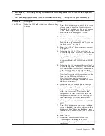
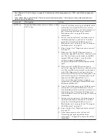
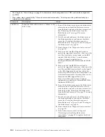
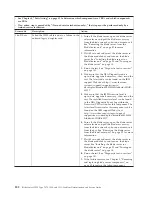
Page 207: ...the blade server on page 14 3 Rerun the test See Diagnostic tools overview on page 101 4 Make sure that the DSA Diagnostic code is up to date upgrade if necessary then rerun the test The latest code c...

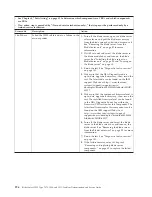
Page 208: ...Diagnostic code is up to date upgrade if necessary then rerun the test The latest code can be found on the IBM support Web site at http www ibm com systems support supportsite wss docdisplay brandind...

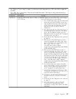
Page 209: ...display brandind 5000008 lndocid MIGR 63017 5 Make sure that the component firmware level is up to date upgrade if necessary then rerun the test The installed firmware level can be found in the DSA Di...

Page 210: ...to date upgrade if necessary then rerun the test The latest code can be found on the IBM support Web site at http www ibm com systems support supportsite wss docdisplay brandind 5000008 lndocid MIGR 6...

Page 211: ...necessary then rerun the test The latest code can be found on the IBM support Web site at http www ibm com systems support supportsite wss docdisplay brandind 5000008 lndocid MIGR 63017 5 Make sure t...

Page 212: ...ibm com systems support supportsite wss docdisplay brandind 5000008 lndocid MIGR 63017 5 Make sure that the IMM firmware level is up to date upgrade if necessary then rerun the test The installed fir...

Page 213: ...Web site at http www ibm com systems support supportsite wss docdisplay brandind 5000008 lndocid MIGR 63017 5 Make sure that the IMM firmware level is up to date upgrade if necessary then rerun the t...

Page 214: ...systems support supportsite wss docdisplay brandind 5000008 lndocid MIGR 63017 5 Make sure that the IMM firmware level is up to date upgrade if necessary then rerun the test The installed firmware le...

Page 215: ...Web site at http www ibm com systems support supportsite wss docdisplay brandind 5000008 lndocid MIGR 63017 5 Make sure that the IMM firmware level is up to date upgrade if necessary then rerun the t...

Page 216: ...www ibm com systems support supportsite wss docdisplay brandind 5000008 lndocid MIGR 63017 5 Make sure that the IMM firmware level is up to date upgrade if necessary then rerun the test The installed...

Page 217: ...e latest code can be found on the IBM support Web site at http www ibm com systems support supportsite wss docdisplay brandind 5000008 lndocid MIGR 63017 6 Make sure that the IMM firmware level is up...

Page 218: ...com systems support supportsite wss docdisplay brandind 5000008 lndocid MIGR 63017 5 Make sure that the IMM firmware level is up to date upgrade if necessary then rerun the test The installed firmwar...

Page 219: ...Event Log within the Firmware VPD section for this component The latest level firmware for this component can be found on the IBM support Web site at http www ibm com support docview wss uid psg1MIGR...

Page 220: ...upgrade if necessary then rerun the test The latest code can be found on the IBM support Web site at http www ibm com support docview wss uid psg1SERV DSA 3 Make sure that the system firmware level i...

Page 221: ...at http www ibm com support docview wss uid psg1SERV DSA 3 Make sure that the system firmware level is up to date upgrade if necessary then rerun the test The installed firmware level can be found in...

Page 222: ...on the IBM support Web site at http www ibm com support docview wss uid psg1SERV DSA 3 Make sure that the system firmware level is up to date upgrade if necessary then rerun the test The installed fi...

Page 223: ...ponding turn off and restart the blade server then rerun the test See Turning off the blade server on page 14 Turning on the blade server on page 14 and Diagnostic tools overview on page 101 2 Make su...

Page 224: ...blade server components on page 49 to replace the failed component 4 Rerun the test 201 815 xxx Aborted the memory self test because of a programming error in the Quick Memory menu item selection pro...

Page 225: ...ilure remains refer to Chapter 5 Removing and replacing blade server components on page 49 to replace the failed component 201 819 xxx Aborted the memory self test because the START END address ranges...

Page 226: ...www ibm com support docview wss uid psg1MIGR 63017 4 If the component failure remains refer to Chapter 5 Removing and replacing blade server components on page 49 to replace the failed component 201...

Page 227: ...og within the Firmware VPD section for this component The latest level firmware for this component can be found on the IBM support Web site at http www ibm com support docview wss uid psg1MIGR 63017 4...

Page 228: ...latest code can be found on the IBM support Web site at http www ibm com support docview wss uid psg1SERV DSA 3 Make sure that the system BIOS firmware is at the latest level upgrade if necessary the...

Page 229: ...ver on page 14 4 Make sure that the DSA Diagnostic code is at the latest level then rerun the test Diagnostic tools overview on page 101 The latest code can be found on the IBM support Web site at htt...

Page 230: ...information about replacing the optical drive media tray 3 Make sure that the cable for the optical drive is not damaged then replace the cable if damage is present See your BladeCenter documentation...

Page 231: ...n for information about the optical drive media tray 5 Make sure that the cable for the optical drive is not damaged and replace the cable if damage is present See your BladeCenter documentation for i...

Page 232: ...s not detected 1 Insert a new CD or DVD into the drive and wait for 15 seconds for the media to be recognized then rerun the test See Diagnostic tools overview on page 101 2 Make sure that the cable f...

Page 233: ...eCenter documentation for information about the optical drive media tray 3 Make sure that the cable for the optical drive is not damaged and replace the cable if damage is present See your BladeCenter...

Page 234: ...drive is not damaged then replace the cable if damage is present See your BladeCenter documentation for information about replacing the optical drive media tray 4 Make sure that the DSA Diagnostic co...

Page 235: ...ation for information about the optical drive media tray 3 Make sure that the cable for the optical drive is not damaged then replace the cable if damage is present See your BladeCenter documentation...

Page 236: ...for this component The latest level firmware for this component can be found on the IBM support Web site at http www ibm com support docview wss uid psg1MIGR 63017 4 Rerun the test 5 If the component...

Page 237: ...ry count threshold is passed during an operation to scan the bar code on a cartridge before the operation succeeds This flag is internally cleared when another bar code scanning operation is attempted...

Page 238: ...server cover See Removing the blade server cover on page 55 17 Move the UEFI boot block recovery switch SW1 5 to the OFF position see System board switches on page 16 18 Replace the cover and reinsta...

Page 239: ...ent module The default setting is disable 12 Select Blade Tasks Firmware update and select the blade server you want to recover 13 Use the browse button to point to the UEFI update file 14 Click the U...

Page 240: ...rmware update by following the instructions that are in the firmware update package readme file 4 Restart the server see Turning off the blade server on page 14 and Turning on the blade server on page...

Page 241: ...t the SAS devices are configured correctly Solving shared BladeCenter resource problems Use this information to diagnose and resolve shared BladeCenter resource issues Problems with BladeCenter shared...

Page 242: ...likely a problem with the blade server See Keyboard or mouse problems on page 168 Media tray problems Use this information to diagnose and resolve media tray issues for the blade server To check for...

Page 243: ...s working properly 6 For problems that affect one or more of the removable media drives a Reseat the following components 1 Removable media drive cable if applicable 2 Removable media drive 3 Media tr...

Page 244: ...n problems on page 171 Power problems Use this information to diagnose and resolve power issues with the blade server To check for power problems make sure that v The LEDs on all the BladeCenter power...

Page 245: ...tests show that the monitor is working correctly consider the location of the monitor Magnetic fields around other devices such as transformers appliances fluorescent lights and other monitors can cau...

Page 246: ...the UEFI code is damaged see Recovering from a UEFI update failure on page 223 Check the LEDs on all the power supplies of the BladeCenter unit in which the blade server is installed If the LEDs indic...

Page 247: ...del v Microprocessor and hard disk drive upgrades v Failure symptoms Does the blade server fail the diagnostic tests What occurs When Where Does the failure occur on a single server or on multiple ser...

Page 248: ...234 BladeCenter HS22 Type 7870 1936 and 1911 Problem Determination and Service Guide...

Page 249: ...You can obtain the latest downloads for your IBM product from http www ibm com systems support supportsite wss docdisplay brandind 5000008 lndocid MIGR 63017 v If you have installed new hardware or so...

Page 250: ...World Wide Web On the World Wide Web up to date information about IBM systems optional devices services and support is available at http www ibm com systems support You can find the most up to date p...

Page 251: ...are available Monday through Friday from 9 a m to 6 p m IBM Taiwan product service Use this information to contact IBM Taiwan product service IBM Taiwan product service contact information IBM Taiwan...

Page 252: ...238 BladeCenter HS22 Type 7870 1936 and 1911 Problem Determination and Service Guide...

Page 253: ...E IMPLIED WARRANTIES OF NON INFRINGEMENT MERCHANTABILITY OR FITNESS FOR A PARTICULAR PURPOSE Some states do not allow disclaimer of express or implied warranties in certain transactions therefore this...

Page 254: ...tended to be used in a public services network CD or DVD drive speed is the variable read rate Actual speeds vary and are often less than the possible maximum When referring to processor storage real...

Page 255: ...the device IBM may condition provision of repair or replacement of devices or parts on implementation of appropriate remedial measures to mitigate such environmental contamination Implementation of su...

Page 256: ...ent is operated in a commercial environment This equipment generates uses and can radiate radio frequency energy and if not installed and used in accordance with the instruction manual may cause harmf...

Page 257: ...rtment M456 IBM Allee 1 71137 Ehningen Germany Telephone 49 7032 15 2937 Email tjahn de ibm com Germany Class A statement Deutschsprachiger EU Hinweis Hinweis f r Ger te der Klasse A EU Richtlinie zur...

Page 258: ...ational Business Machines Corp New Orchard Road Armonk New York 10504 914 499 1900 Der verantwortliche Ansprechpartner des Herstellers in der EU ist IBM Deutschland Technical Regulations Department M4...

Page 259: ...Communications Commission KCC statement This is electromagnetic wave compatibility equipment for business Type A Sellers and users need to pay attention to it This is for any areas other than home Rus...

Page 260: ...246 BladeCenter HS22 Type 7870 1936 and 1911 Problem Determination and Service Guide...

Page 261: ...ID array 36 configuring your blade server 21 configuring your server 28 connectors 15 I O expansion card 15 memory 15 microprocessor 15 SAS hard disk drives 15 system board 15 contamination particulat...

Page 262: ...sages 173 removable media drive 179 S BRD 185 SAS storage drive error 185 service processor 227 shared resource problems 227 software 180 storage drive self tests 217 000 000 222 217 800 xxx 222 217 9...

Page 263: ...path diagnostics LEDs 185 BladeCenter GPU expansion unit 188 light path diagnostics panel 18 light path diagnostics switch 17 light path LED locations 183 expansion unit 187 load default settings 22...

Page 264: ...Center HS22 9 start options 22 starting the blade server 14 startup sequence options 22 startup sequence setting 22 static electricity 50 static sensitive devices handling 50 stopping the blade server...

Page 265: ...W Web site ServerGuide 31 Windows IPMI device driver 38 WOL disable switch 17 wrong characters 170 Index 251...

Page 266: ...252 BladeCenter HS22 Type 7870 1936 and 1911 Problem Determination and Service Guide...

Page 267: ......

Page 268: ...Part Number 90Y5614 Printed in USA 1P P N 90Y5614...

Reviews: