b.
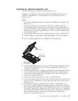
Loosen the screws and remove the retention bracket, then disconnect the
cable from the expansion-unit system board (B).
c.
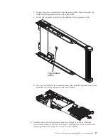
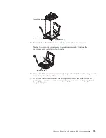
Locate the tray-release button on the bottom of the expansion unit.
Tray release
button
d.
Press in and hold the tray-release button; then, pull the expansion-unit riser
assembly out of the expansion-unit system board.
6.
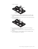
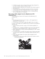
Carefully turn over the expansion-unit riser assembly, and use a Phillips
screwdriver to remove the four non-captive retaining screws, as shown in the
following illustration. Store the screws in a safe location.
Chapter 5. Removing and replacing blade server components
87
Summary of Contents for 7870B4U
Page 1: ...BladeCenter HS22 Type 7870 1936 and 1911 Problem Determination and Service Guide...
Page 2: ......
Page 3: ...BladeCenter HS22 Type 7870 1936 and 1911 Problem Determination and Service Guide...
Page 14: ...xii BladeCenter HS22 Type 7870 1936 and 1911 Problem Determination and Service Guide...
Page 20: ...6 BladeCenter HS22 Type 7870 1936 and 1911 Problem Determination and Service Guide...
Page 34: ...20 BladeCenter HS22 Type 7870 1936 and 1911 Problem Determination and Service Guide...
Page 248: ...234 BladeCenter HS22 Type 7870 1936 and 1911 Problem Determination and Service Guide...
Page 252: ...238 BladeCenter HS22 Type 7870 1936 and 1911 Problem Determination and Service Guide...
Page 260: ...246 BladeCenter HS22 Type 7870 1936 and 1911 Problem Determination and Service Guide...
Page 266: ...252 BladeCenter HS22 Type 7870 1936 and 1911 Problem Determination and Service Guide...
Page 267: ......
Page 268: ...Part Number 90Y5614 Printed in USA 1P P N 90Y5614...


