4.
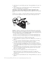
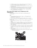
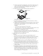
Use your hand to keep the bezel assembly tight against the blade server; then,
rotate the blade server so that the bottom is now facing up.
5.
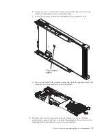
Use a screwdriver to install the four screws that secure the bezel assembly to
the blade server. It is recommended to use the same screws that were removed
when the bezel assembly was removed.
6.
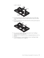
Orient the blade server so that the bottom of the blade server is down.
7.
Install the optional expansion unit, if you removed one from the blade server
(see “Installing an optional expansion unit” on page 85 for instructions).
8.
Install the cover onto the blade server (see “Closing the blade server cover” on
page 56).
9.
Install the blade server into the BladeCenter unit (see “Installing the blade
server in a BladeCenter unit” on page 53).
Removing the control panel
Use this information to remove the control panel from the blade server.
Note:
1.
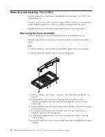
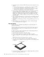
The following illustration shows the locations of the control panel on the
system board.
2.
The illustrations in this document might differ slightly from your hardware.
To remove the control panel, complete the following steps.
Control panel connector
Control panel cable
1.
Before you begin, read “Safety” on page v and “Installation guidelines” on
page 49.
2.
If the blade server is installed in a BladeCenter unit, remove it (see “Removing
the blade server from the BladeCenter unit” on page 52).
3.
Remove the blade server cover (see “Removing the blade server cover” on page
55).
4.
If an optional expansion unit is installed, remove the expansion unit (see
“Removing an optional expansion unit” on page 84).
5.
Remove the bezel assembly (see “Removing the bezel assembly” on page 80).
6.
Locate the control-panel connector on the system board (see “Blade server
connectors” on page 15).
7.
Using your fingers, pull the control-panel cable out of the connector; then lift
the control panel from the blade server.
8.
If you are instructed to return the control panel, follow all packaging
instructions, and use any packaging materials for shipping that are supplied to
you.
82
BladeCenter HS22 Type 7870, 1936, and 1911: Problem Determination and Service Guide
Summary of Contents for 7870B4U
Page 1: ...BladeCenter HS22 Type 7870 1936 and 1911 Problem Determination and Service Guide...
Page 2: ......
Page 3: ...BladeCenter HS22 Type 7870 1936 and 1911 Problem Determination and Service Guide...
Page 14: ...xii BladeCenter HS22 Type 7870 1936 and 1911 Problem Determination and Service Guide...
Page 20: ...6 BladeCenter HS22 Type 7870 1936 and 1911 Problem Determination and Service Guide...
Page 34: ...20 BladeCenter HS22 Type 7870 1936 and 1911 Problem Determination and Service Guide...
Page 248: ...234 BladeCenter HS22 Type 7870 1936 and 1911 Problem Determination and Service Guide...
Page 252: ...238 BladeCenter HS22 Type 7870 1936 and 1911 Problem Determination and Service Guide...
Page 260: ...246 BladeCenter HS22 Type 7870 1936 and 1911 Problem Determination and Service Guide...
Page 266: ...252 BladeCenter HS22 Type 7870 1936 and 1911 Problem Determination and Service Guide...
Page 267: ......
Page 268: ...Part Number 90Y5614 Printed in USA 1P P N 90Y5614...


