___,
-0 . 6 V
1
I
I
I
I
I
I
70ns
r-
\
�
!\_
I
:::::
I
- 1 . B V
�
1 00us
�
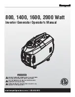
Figure 1 0.3-14. Width Generator ramp signal
4.
Check the signal being sent to the slope generator IC at TP3
against Figure
10.3- 15.
-0 . 2V
-0 . B V
DBL MODE
�
2 00us
�
Figure 1 0.3-1 5. Width Generator output
5.
Check the Width Generator operation against Table
10.3- 14
and
Table
10.3- 1 5
Table 1 0.3-14. Width Generator Operation
U240 Pin Mnemonic
5 WIDC
2 ERW
10 WIC
11 to 18 LD7 - LDO
R245
Description
State
Width control voltage input
L
Width error output signal
L
Width input store select
See Table 10 .3-1
Data to be latched into
See Table 10 .3-2
the input store of U240
Width Vernier Current
See Table 10.3-15
6.
Verify that voltage at
U240
pins
1, 4
and
5
are at virtual ground
(min.
-40
mV max.
0
V)
1 0.3-20 Servicing the Timing and
Slope Generators
Summary of Contents for 8112A
Page 6: ......
Page 24: ......
Page 36: ......
Page 44: ......
Page 70: ......
Page 92: ......
Page 144: ...8 32 Testing Performance ...
Page 176: ......
Page 190: ......
Page 194: ...10 2 4 Servicing the Power Supply ...
Page 196: ......
Page 197: ......
Page 216: ......
Page 240: ...10 4 16 Servicing the Shaper and Output Amplifier ...
Page 242: ...A R l BD RY MR I N 1 2 7 I I IJt 51 CR1 B e i 1 _ _ _ _ 20 ...
Page 244: ......
Page 251: ......
Page 262: ...A B A2 ED RY CONTROL ...
Page 270: ......
Page 290: ...R B c R3 BD RY M I CROPROCESSOR 1 2 3 FIGURE 1 0 7 8 ...
Page 294: ... 8 X2l 2 X2 Figure A 1 Mechanical Parts 1 A 2 Replaceable Parts ...
Page 295: ...MP MP3 MP MP2 MP4 MPS MP 1 2 MPS MP MP I B ElElElEl Replaceable Parts A 3 ...
Page 334: ......
Page 378: ...Figure B 14 Mechanical Parts 1 B 44 Backdating ...
Page 380: ......
Page 382: ......
Page 402: ......