Mode Selection
Depending on the control mode selected, the output signal may be
either Period, Delay, Width, or High Level controlled, by an external
voltage applied to the CTRL INPUT.
Note
4-8 Operating
The control mode can be cycled through available options by pressing
the key below the mode indicators and the currently active mode
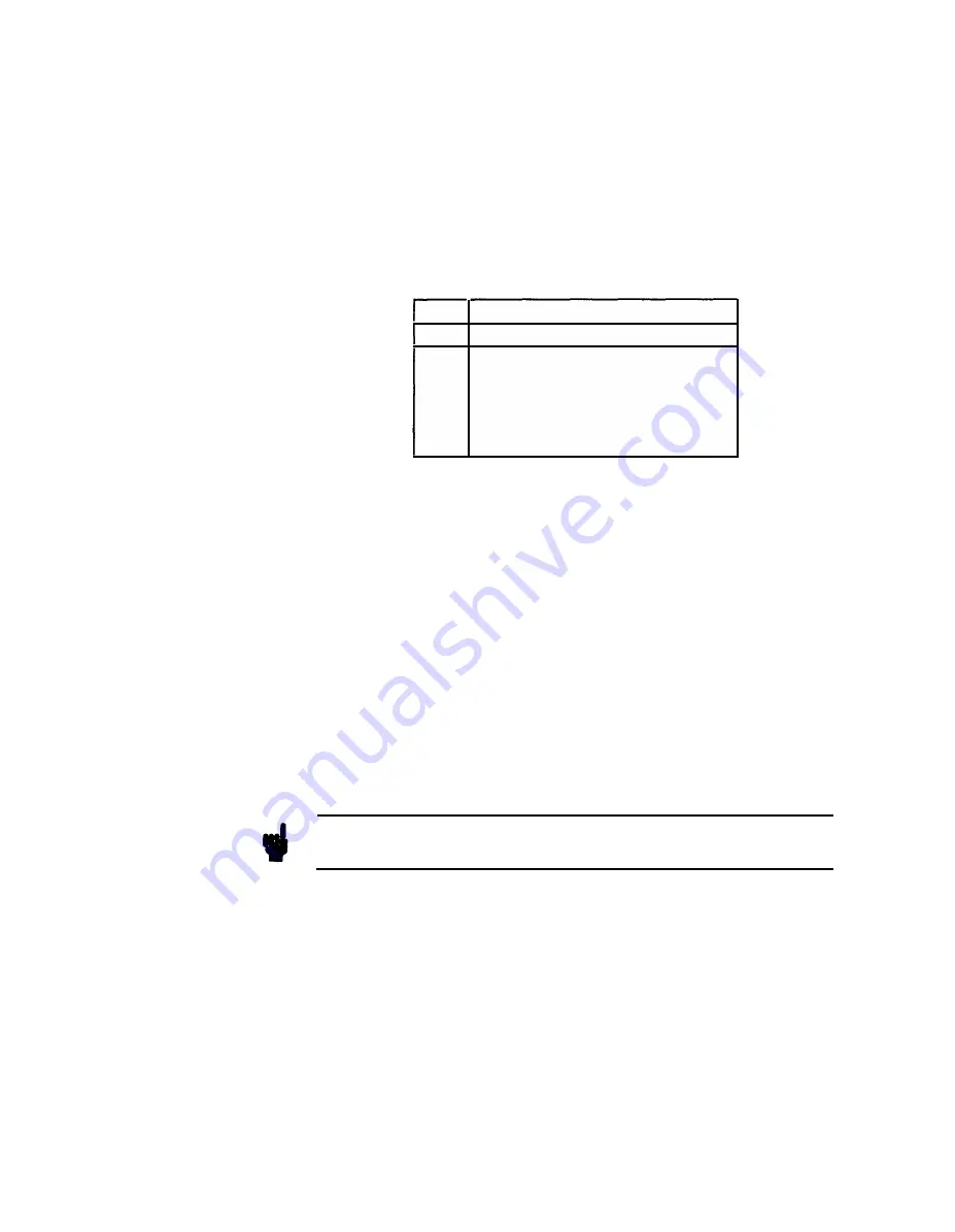
is shown by an LED indicator. Table 4- 1 indicates the permitted
combinations of control and operating modes.
Table 4-1. Operating/Control Mode Combinations
CTRL
MODE
NORM TRIG GATE EWID EBUR
PERC
x
x
x
DELC
x
x
x
x
DBLC
x
x
x
x
WIDC
x
x
x
x
HILC
x
x
x
x
x
Period Control (PERC)
Control input sensitivity is + LO V to + 10.0 V ( +2.0 V to +10 V in
the 20 ns to 100 ns range) and period ranges from 20 ns to 1 s are
available in eight non-overlapping decades. See Figure 4-5.
The decade is selected by setting PER within that decade, i .e.
PER=3 µs would mean than control input voltage cycling between
1 V and 10 V, will control the period between 1 µs and 10 µs.
Whatever the value you select for PER, the upper limit for that
decade is displayed ( 10 µs if 3 µs was selected as above). The vernier
keys are inoperative and the Range key is used to change range.
Delay Control (DELC)
Control input sensitivity is + LO V to +10.0 V. Minimum delay is 75
ns and a maximum delay of 1 second is obtainable.
In
DBL mode the time
between
pulses will be varied by the control
input, when DELC is selected.
See Figure 4-5.
Width Control (WIDC)
Control input sensitivity is + LO V to + 10.0 V and width range 10 ns
to 1 s in eight non-overlapping decades. See Figure 4-5.
High Level Control (HILC)
High Level control is available in the range -8.0 V to +8.0 V. It is
important to note that while the Low Level (LOL) value can be
set to a maximum of +
7.95
V in 50 m V steps, the LIMIT facility
Summary of Contents for 8112A
Page 6: ......
Page 24: ......
Page 36: ......
Page 44: ......
Page 70: ......
Page 92: ......
Page 144: ...8 32 Testing Performance ...
Page 176: ......
Page 190: ......
Page 194: ...10 2 4 Servicing the Power Supply ...
Page 196: ......
Page 197: ......
Page 216: ......
Page 240: ...10 4 16 Servicing the Shaper and Output Amplifier ...
Page 242: ...A R l BD RY MR I N 1 2 7 I I IJt 51 CR1 B e i 1 _ _ _ _ 20 ...
Page 244: ......
Page 251: ......
Page 262: ...A B A2 ED RY CONTROL ...
Page 270: ......
Page 290: ...R B c R3 BD RY M I CROPROCESSOR 1 2 3 FIGURE 1 0 7 8 ...
Page 294: ... 8 X2l 2 X2 Figure A 1 Mechanical Parts 1 A 2 Replaceable Parts ...
Page 295: ...MP MP3 MP MP2 MP4 MPS MP 1 2 MPS MP MP I B ElElElEl Replaceable Parts A 3 ...
Page 334: ......
Page 378: ...Figure B 14 Mechanical Parts 1 B 44 Backdating ...
Page 380: ......
Page 382: ......
Page 402: ......


