4
_____________________________________________________________________________________________
1.2 Identification of Controls and Indicators
______________________________________________________________________________________________
14
3
4
1
2
8
9
6
5
7
12
10
11
13
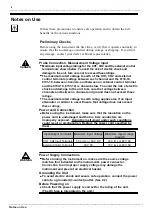
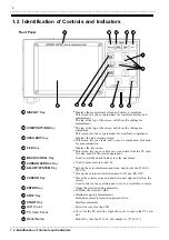
Front Panel
1
DISPLAY
Key
Displays the measurement screen and shows a waveform.
This screen lets you set parameters for waveform display and
measurement.
The tag at the top of the screen will show the settings for
measurement.
2
COMP SETTING
Key
The tag at the top of the screen will show the settings for
comparison.
This screen lets you set parameters for waveform comparison.
3
AREA EDIT
Key
Displays the area creation screen.
This screen lets you create, edit, or save a comparison area used
for area comparison.
4
FILE
Key
Displays the file screen.
This screen lets you save data on or read data from the PC card.
It is also used for file-related operations.
5
WAVE SCROLL
Key
Used to scroll back and forth across the waveform.
6
CURSOR SCROLL
Key
Used to move cursors A and B.
7
ADJUST/SYSTEM
Key
Sets up the zero-adjustment and clock and checks the 8730-10,
8731-10.
Sets up the external control terminals, LAN, and RS-232C.
8
CURSOR
Key
Moves the selector cursor up and down and right and left on the
screen.
Used to select a tag or setting and to move a waveform or cursor.
9
ENTER
Key
Opens the selected setting parameter.
Confirms the selected value.
10
STOP
Key
Interrupts ongoing measurement.
Terminates measurement when pressed twice.
11
START
Key
Starts measurement.
12
LCD Cover
Protective cover for the LCD
13
PC Card Cover
Cover for the PC card slot. Open the cover to expose the PC card
slot.
14
Model Name
Model No. (For the 8731-10, this number is "8731-10.")
1.2 Identification of Controls and Indicators


