62
_____________________________________________________________________________________________
4.3 Details of Input Setting
______________________________________________________________________________________________
4.3.1 Range
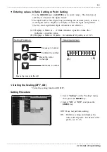
Setting Screen:
Unit
CH1 (CH2)
Range (100 mV, 200 mV, 500 mV, 1 V, 2 V, 5 V)
NOTE
4.3 Details of Input Setting
This section explains various setting for "
Unit
" tab.
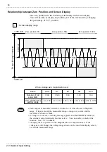
Sets the voltage axis range for input signals.
The values shown in the range menu represent the voltages per DIV in the
voltage axis direction.
After the range has been changed, perform zero adjustment (see 7.2.1).
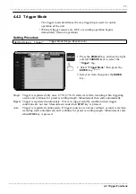
Setting Procedure
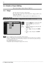
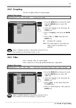
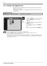
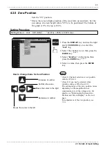
1. Press the
DISPLAY
key and use the right
and left
CURSOR
keys to select the
"
Unit
" tag.
2
.
Select the channel to set, then press the
ENTER
key.
(Note 1)
3. Select "
Range
", then press the
ENTER
key.
4. Select a value, then press the
ENTER
key.
(Note 1) Channel selection is not possible with the 8730-10.
Select a suitable range for input. Each range is measurable between -10 times and +11 times the
set range. If measurement exceeds this range, a range-over occurs and the waveform will not be
correctly displayed. (See 4.3.5)
The currently selected range is shown in red.
Changing the range also changes the trigger level. (See 4.4)


