60
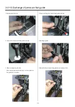
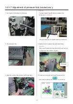
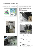
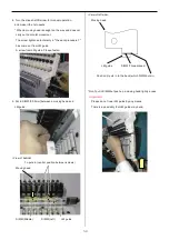
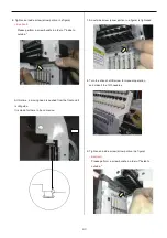
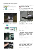
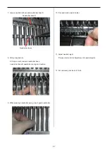
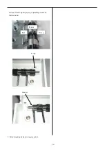
6. Tighten an inside screw (arrow portion in a figure).
<important>
Please perform a screw bundle in order of "inside to
outside."
At this time, a moving head is pushed from the front and it
is LM guide.
It is made for there to be no crevice.
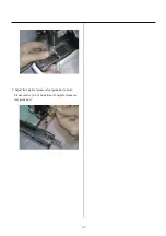
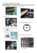
7. An outside screw (arrow portion in a figure) is tightened.
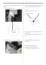
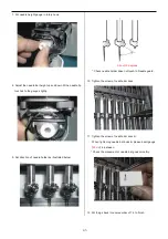
8. Turn the drive shaft B screw for manual operation,
and make it the 12th needles.
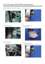
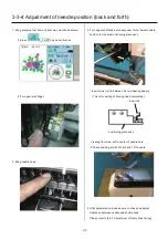
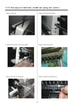
9. Tighten an inside screw (arrow portion in a figure).
<important>
Please perform a screw bundle in order of "inside to
outside."
Summary of Contents for HCS2-1201-30
Page 1: ...Maintenance Manual for Embroidery Machine HCS2 1201 30 Version 2 3 HappyJapan Inc...
Page 154: ...153 5 1 1 Electrical connection diagram except for Rev A...
Page 155: ...154 5 1 1 Electrical connection diagram except for Rev A...
Page 156: ...155 5 1 2 List of electrical connection diagrams except for Rev A...
Page 157: ...156 5 1 3 Electrical connection diagram for Rev A...
Page 158: ...157 5 1 3 Electrical connection diagram for Rev A...
Page 159: ...158 5 1 4 List of electrical connection diagrams for Rev A...
Page 160: ...159 5 2 1 Connection of inverter 100V Inverter set...
Page 161: ...160 5 2 2 Connection of inverter 200V Inverter set...
Page 165: ...160c HCD8116 TP switch board ass y 6 5 265 2 1 6 7 257...

