42
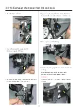
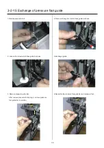
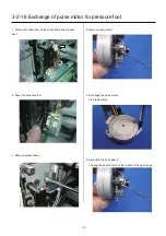
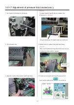
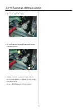
3-2-13 Exchange of pressure foot link and block
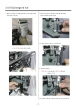
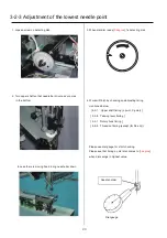
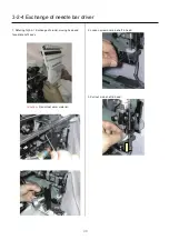
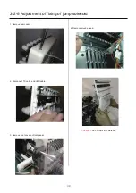
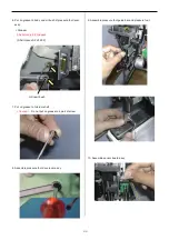
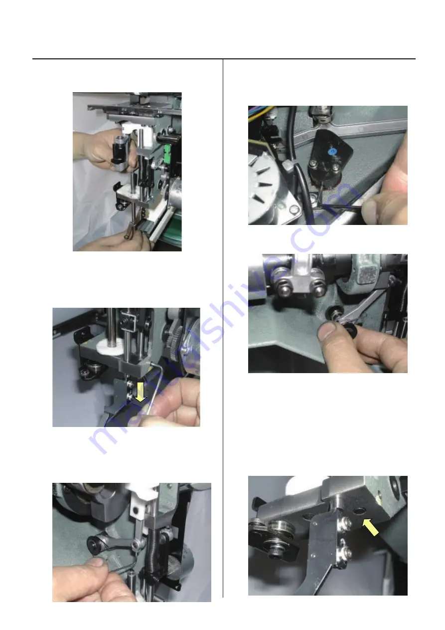
1. Move the head shaft lower.
2. Loosen the screw which fixes guide shaft
then move the guide shaft lower.
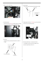
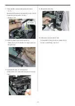
3. If you exchange block ass’y, loosen the screw which fixes
pressure foot link A then remove block ass’y.
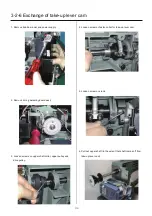
4. If you remove the pressure foot link B ass’y, first remove
the pressure foot cam collar and pressure foot drive cam.
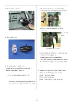
5. Remove pressure foot link B ass’y.
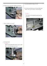
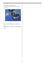
6. Assemble the parts by opposite procedure to terminate this
exchange.
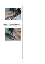
When assembling each unit, please refer to each
procedure Instruction for assemble adjustment.
<Attention>
Position of guide shaft is attached to lowest and the side
of Head.
Summary of Contents for HCS2-1201-30
Page 1: ...Maintenance Manual for Embroidery Machine HCS2 1201 30 Version 2 3 HappyJapan Inc...
Page 154: ...153 5 1 1 Electrical connection diagram except for Rev A...
Page 155: ...154 5 1 1 Electrical connection diagram except for Rev A...
Page 156: ...155 5 1 2 List of electrical connection diagrams except for Rev A...
Page 157: ...156 5 1 3 Electrical connection diagram for Rev A...
Page 158: ...157 5 1 3 Electrical connection diagram for Rev A...
Page 159: ...158 5 1 4 List of electrical connection diagrams for Rev A...
Page 160: ...159 5 2 1 Connection of inverter 100V Inverter set...
Page 161: ...160 5 2 2 Connection of inverter 200V Inverter set...
Page 165: ...160c HCD8116 TP switch board ass y 6 5 265 2 1 6 7 257...

