63
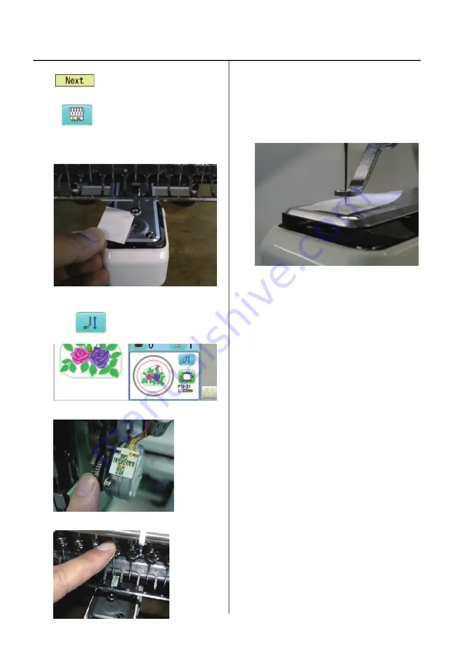
3-3-5 Check of needle position
1.
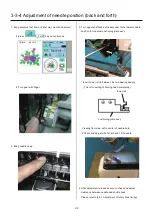
A main switch is turned on.
The
is pressed and it changes into an
operation state.
2. Press
and make it the 4th needles.
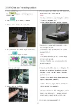
3. Stick a seal on needle hole of a needle plate.
4. Bring pressure foot down. (Either way mentioned below)
(1)press
key on control box.
(2)Turn gear with finger.
5. Lower a needle bar with a finger.
6. Turn an upper axis up to [302 degrees - 303 "], and it is the
needle mark to a seal. A hole is made.
<Note>
Needle point will become large if the angle of a dial disc
is made into 304 degrees or more.
An exact needle position check becomes impossible.
7. Reverse-rotate an upper axis, raise a needle bar, and
unite with C [275 degrees].
(It returns to 303 degrees-> 220", and unites with 275
degrees after that.)
<Note>
If a top axis is right-rotated, a needle will enter deeply,
and needle hole is greatly.
It becomes. Therefore, an exact needle position check
becomes impossible.
8. 1st needle and the 12th needles are to 302 degrees - 303
degrees about an upper axis by the above-mentioned
procedure. It turns, a needle is lowered and a needle
position is checked.
It will be O.K. if the needle point goes into the seal hole
made by the 6th needles at this time.
* If “NG”. Please adjust again, follow to [3-3-3 Asemble
the moving head] of procedure 6-10.
The order which the screw which is fixing the move head
fastens -- from an inner side. If it does not carry out
correctly outside, a needle position will shift -- it is –
9. Un-stick a seal on needle plate to finish.
Summary of Contents for HCS2-1201-30
Page 1: ...Maintenance Manual for Embroidery Machine HCS2 1201 30 Version 2 3 HappyJapan Inc...
Page 154: ...153 5 1 1 Electrical connection diagram except for Rev A...
Page 155: ...154 5 1 1 Electrical connection diagram except for Rev A...
Page 156: ...155 5 1 2 List of electrical connection diagrams except for Rev A...
Page 157: ...156 5 1 3 Electrical connection diagram for Rev A...
Page 158: ...157 5 1 3 Electrical connection diagram for Rev A...
Page 159: ...158 5 1 4 List of electrical connection diagrams for Rev A...
Page 160: ...159 5 2 1 Connection of inverter 100V Inverter set...
Page 161: ...160 5 2 2 Connection of inverter 200V Inverter set...
Page 165: ...160c HCD8116 TP switch board ass y 6 5 265 2 1 6 7 257...

