33
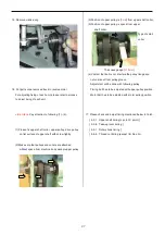
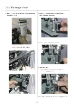
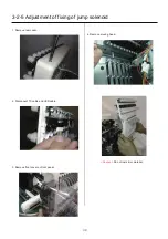
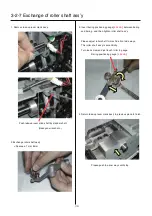
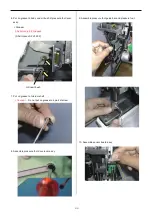
5. Remove jump solenoid ass’y.
6. Install good parts.
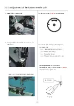
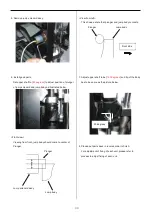
Set upper shaft to [
80 degrees
] to adjust position of plunger
of jump solenoid and jump body as illustrated below.
<Front view>
Viewing from front, jump body should come to center of
Plunger.
Plunger
Jump solenoid ass’y
Jump body
<View from left>
This shows a state that plunger and jump body contacts.
Plunger Jump body
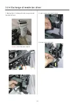
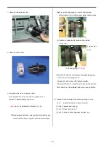
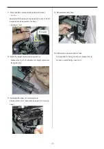
7. Adjust upper shaft to be [
180 degrees
] and tip of the body
has to be same as the picture below.
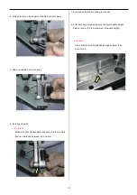
8. Please put parts back in reverse order to finish.
For adjustment of fixing of each unit, please refer to
process to adjust fixing of each unit.
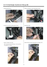
90 degrees
Front side
Summary of Contents for HCS2-1201-30
Page 1: ...Maintenance Manual for Embroidery Machine HCS2 1201 30 Version 2 3 HappyJapan Inc...
Page 154: ...153 5 1 1 Electrical connection diagram except for Rev A...
Page 155: ...154 5 1 1 Electrical connection diagram except for Rev A...
Page 156: ...155 5 1 2 List of electrical connection diagrams except for Rev A...
Page 157: ...156 5 1 3 Electrical connection diagram for Rev A...
Page 158: ...157 5 1 3 Electrical connection diagram for Rev A...
Page 159: ...158 5 1 4 List of electrical connection diagrams for Rev A...
Page 160: ...159 5 2 1 Connection of inverter 100V Inverter set...
Page 161: ...160 5 2 2 Connection of inverter 200V Inverter set...
Page 165: ...160c HCD8116 TP switch board ass y 6 5 265 2 1 6 7 257...

