83
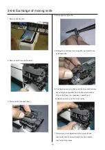
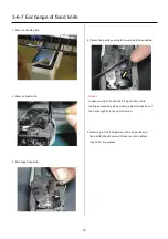
3-6-1 Assemble the arm ass’y
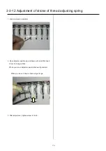
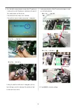
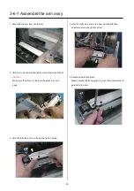
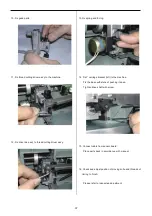
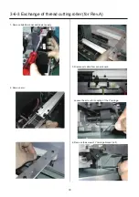
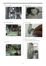
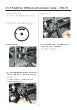
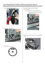
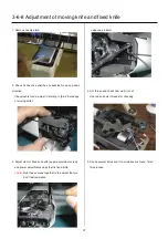
1. Assemble the arm ass’y tentatively.
2. Hold arm to backward and tighten only hithermost
screw.
<Caution>
Make sure that there is clearance between arm and
body.
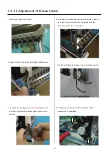
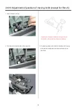
3. Hold the left side of arm to body and tighten screw.
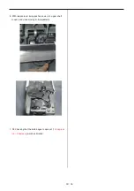
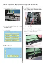
4. Hold the right side of arm to arrow pointed direction
at below picture and tighten screw.
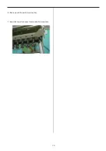
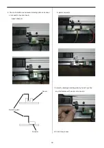
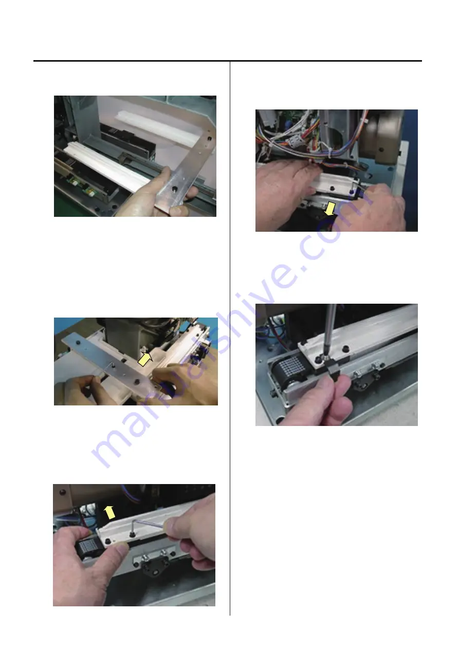
5. Assemble detecting plate.
Make sure that detecting plate is mount perpendicular and
parallel to the arm.
Summary of Contents for HCS2-1201-30
Page 1: ...Maintenance Manual for Embroidery Machine HCS2 1201 30 Version 2 3 HappyJapan Inc...
Page 154: ...153 5 1 1 Electrical connection diagram except for Rev A...
Page 155: ...154 5 1 1 Electrical connection diagram except for Rev A...
Page 156: ...155 5 1 2 List of electrical connection diagrams except for Rev A...
Page 157: ...156 5 1 3 Electrical connection diagram for Rev A...
Page 158: ...157 5 1 3 Electrical connection diagram for Rev A...
Page 159: ...158 5 1 4 List of electrical connection diagrams for Rev A...
Page 160: ...159 5 2 1 Connection of inverter 100V Inverter set...
Page 161: ...160 5 2 2 Connection of inverter 200V Inverter set...
Page 165: ...160c HCD8116 TP switch board ass y 6 5 265 2 1 6 7 257...

