


Part No. 1268494 S-100 • S-105 • S-120 • S-125
6-21
March 2017
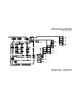
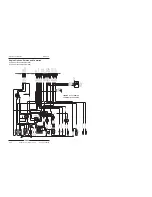
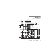
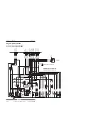
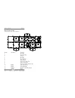
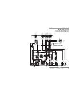
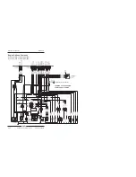
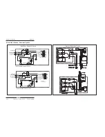
Section 6 • Schematics
87a
87
P57PBD
P57PBD
S62BST
O
C60AXEX
S59CNBK
C61AXRT
88
P53LS
LSB6S
CABLE TENSION
P63LS
S62BSTO
LSB3RS
BOOM RETRACT
P53LS
C60AXEX
TCON/J2/11
TCON/J2/9
TCON/J2/7
TCON/J2/12
TCON/J2/10
TCON/J2/8
DCON/J1/3
MONITORED BY ECU
S62BSTO
C60AXEX
P58LS
P63LS
P_10
GND
OUT 1
OUT 2
PWR
STAT
IN 1
IN 2
NFET
D17
P_11
D13
P_9B
NFET
GND
OUT 1
OUT 2
PWR
STAT
IN 1
IN 2
NFET
GND
OUT 1
OUT 2
PWR
STAT
IN 1
IN 2
30
86
TCON/J2/5
LSB8AS
50 DEGREES
P58LS
SJ2
SJ1
LSB7DS
BOOM DOWN
P53LS
LSB2RS
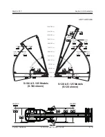
101' (30.8 m)
P53LS
P57PBD
P54ENG
40A
P_7R
87a
87
85
86
30
87a
87
85
86
30
87a
87
85
86
30
TCON/J2/4
P_6R2
DCON/J1/3
LSB4ES
80' (24.4 m)
LSAX2ES
AXLE EXTEND
88
88
LSAX1ES
AXLE EXTEND
LSB9AS
65 DEGREES
P53LS
P57PBD
88
88
20 K
R3
D16
P_16
P_7R
5A
VR1
P_7R
TCON/J2/3
P_6R1
TCON/J2/6
P_9A
D14
D23
P_15
P_9A
TO BOOM DOWN VALVE
NFET
PWR
STAT
IN 1
IN 2
TCON/J4/8
GND
OUT 1
OUT 2
TCON/J4/9
TO BOOM EXTEND VAVLE
85
87a
87
30
86
85
87a
87
30
86
85
TCON/J4/7
TO BOOM UP VALVE
TCON/J3/3
TO FUEL SOLENOID
TO ROTATE CCW VALVE
TO ROTATE CCW VALVE
TO ROTATE CW VALVE
GND
OUT 1
OUT 2
PWR
STAT
IN 1
IN 2
GND
OUT 1
OUT 2
PWR
STAT
IN 1
IN 2
PWR
STAT
IN 1
IN 2
PWR
STAT
IN 1
IN 2
TCON/J4/25
TCON/J4/26
GND
OUT 1
OUT 2
NFET
TCON/J4/10
TCON/J3/9
TO STARTER RELAY
GND
OUT 1
OUT 2
NFET
PWR
STAT
IN 1
IN 2
GND
OUT 1
OUT 2
NFET
PWR
STAT
IN 1
IN 2
GND
OUT 1
OUT 2
NFET
TCON/J4/35
TO DRIVE LP RELAY
NFET
GND
OUT 1
OUT 2
PWR
STAT
IN 1
IN 2
NFET
NFET
TO PRIMARY 1 LOCKOUT VALVE
TO PRIMARY 2 LOCKOUT VALVE
TCON/J4/23
TO MULTIFUNCTION VALVE
TCON/J2/24
TCON/J3/2
TCON/J2/23
HI/LO
TO HI/LO SOLENOID
CHOKE
TO TURNTABLE FLOW CONTROL
ROTATE VALVE
TCON/J3/4
TCON/J4/3
TCON/J2/23
TCON/J4/32
TCON/J3/5
TCON/J3/6
NFET
GND
OUT 1
OUT 2
PWR
STAT
IN 1
IN 2
NFET
OUT 1
OUT 2
PWR
STAT
IN 1
IN 2
GND
OUT 1
OUT 2
PWR
STAT
IN 1
IN 2
GND
OUT 1
OUT 2
PWR
STAT
IN 1
IN 2
NFET
NFET
TO REVERSE VALVE
TO FORWARD VALVE
TO AUXILIARY RELAY
TO
TURNTABLE FLOW CONTROL
ROTATE VALVE
CB1
P_14
P_1
1
(P_18)
(P_14)
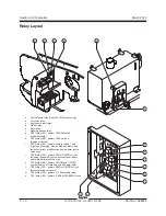
CR17
CR11
CR12
CR10
CR17
CR16
(K2)
(K3)
(K4)
(K6)
(K7)
(K8)
Safety Circuit Schematic
Summary of Contents for S-100
Page 246: ...March 2017 Section 6 Schematics 6 22 Safety Circuit Schematic 6 21 ...
Page 259: ...Section 6 Schematics March 2017 6 35 6 36 Electrical Schematic Generator Options ...
Page 262: ...March 2017 Section 6 Schematics 6 38 6 37 Electrical Schematic 12 kW Generator welder option ...
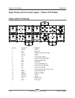
Page 264: ...March 2017 Section 6 Schematics 6 40 Perkins 1104D 44T Engine Electrical Schematic 6 39 ...
Page 265: ...Section 6 Schematics March 2017 6 41 Perkins 854F 34T Engine Electrical Schematic 6 42 ...
Page 268: ...March 2017 Section 6 Schematics 6 44 Perkins 854F 34T Engine Harness 6 45 ...
Page 269: ...Section 6 Schematics March 2017 6 45 Deutz TD2011L04i Engine Electrical Schematic 6 46 ...
Page 271: ...Section 6 Schematics March 2017 6 47 Deutz TD2 9 Engine Electrical Schematic 6 48 ...
Page 274: ...March 2017 Section 6 Schematics 6 50 Deutz TD2 9 Engine Electrical Harness 6 51 ...
Page 276: ...March 2017 Section 6 Schematics 6 52 6 53 Hydraulic Schematic 12 kW Generator welder option ...


