
3 - 60
S-100 • S-105 • S-120 • S-125
Part No. 1268494
March 2017
Section 3 • Repair Procedures
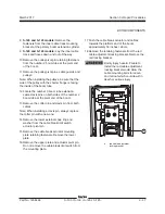
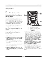
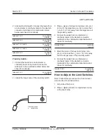
7 Locate the ECM circuit board mounted to the
inside of the platform control box.
Electrocution/burn hazard. Contact
with electrically charged circuits
could result in death or serious
injury. Remove all rings, watches
and other jewelry.
Component damage hazard.
Electrostatic discharge (ESD)
can damage printed circuit board
components. Maintain firm contact
with a metal part of the machine
that is grounded at all times when
handling printed circuit boards OR
use a grounded wrist strap.
8 Remove the ECM circuit board mounting
fasteners.
9 Carefully remove the ECM circuit board from
the platform control box.
7-2
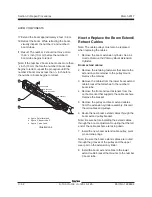
Membrane Decal
The membrane decal is a special decal that
consists of a decal with an electronic membrane
on the backside. The membrane contains touch
sensitive areas that, when pushed, activates the
machine functions. The membrane buttons activate
machine functions similar to toggle switches, but
do not have any moving parts.
How to Replace the Membrane
Decal
1 Turn the key switch at the ground controls to
the
off
position.
2 Push in the Emergency Stop button to the
off
position at both the ground and platform
controls.
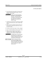
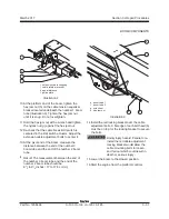
3 Remove the ground control box lid fasteners.
Open the control box lid.
4 Carefully disconnect the two ribbon cables from
the membrane decal at the ECM circuit board.
Electrocution/burn hazard. Contact
with electrically charged circuits
could result in death or serious
injury. Remove all rings, watches
and other jewelry.
Component damage hazard.
Electrostatic discharge (ESD)
can damage printed circuit board
components. Maintain firm contact
with a metal part of the machine
that is grounded at all times when
handling printed circuit boards OR
use a grounded wrist strap.
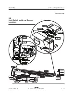
GROUND CONTROLS
Summary of Contents for S-100
Page 246: ...March 2017 Section 6 Schematics 6 22 Safety Circuit Schematic 6 21 ...
Page 259: ...Section 6 Schematics March 2017 6 35 6 36 Electrical Schematic Generator Options ...
Page 262: ...March 2017 Section 6 Schematics 6 38 6 37 Electrical Schematic 12 kW Generator welder option ...
Page 264: ...March 2017 Section 6 Schematics 6 40 Perkins 1104D 44T Engine Electrical Schematic 6 39 ...
Page 265: ...Section 6 Schematics March 2017 6 41 Perkins 854F 34T Engine Electrical Schematic 6 42 ...
Page 268: ...March 2017 Section 6 Schematics 6 44 Perkins 854F 34T Engine Harness 6 45 ...
Page 269: ...Section 6 Schematics March 2017 6 45 Deutz TD2011L04i Engine Electrical Schematic 6 46 ...
Page 271: ...Section 6 Schematics March 2017 6 47 Deutz TD2 9 Engine Electrical Schematic 6 48 ...
Page 274: ...March 2017 Section 6 Schematics 6 50 Deutz TD2 9 Engine Electrical Harness 6 51 ...
Page 276: ...March 2017 Section 6 Schematics 6 52 6 53 Hydraulic Schematic 12 kW Generator welder option ...


