


Part No. 1268494
S-100 • S-105 • S-120 • S-125
3 - 93
March 2017
Section 3 • Repair Procedures
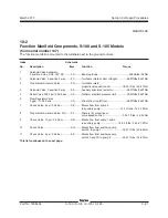
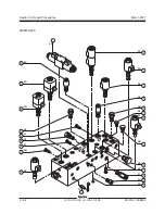
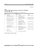
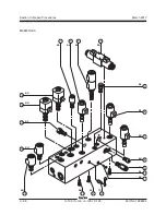
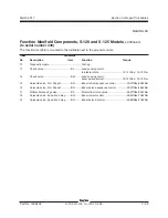
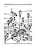
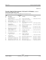
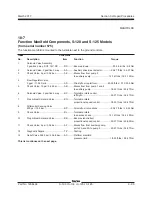
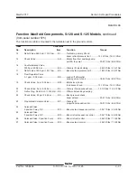
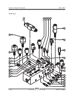
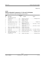
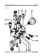
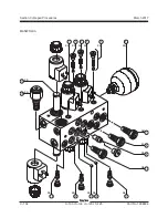
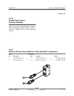
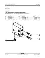
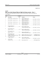
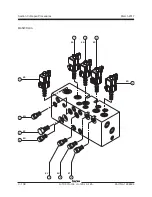
Function Manifold Components, S-120 and S-125 Models
,
continued
(from serial number 431 to 574)
The function manifold is mounted to the turntable next to the ground controls.
Index
Schematic
No.
Description
Item
Function
Torque
13
Counterbalance Valve,
3200 psi / 220.6 bar
........................... BH ..........Primary lift, load holding ....................
30-35 ft-lbs / 41-47 Nm
14
Orifice Plug, 0.040 inch / 1.016 mm
...
BK
..........Differential sensing damping
15
Diagnostic Nipple
............................... TP ..........Testing
16
Proportional Solenoid Valve, N.C.
...... BB ..........
Boom extend/retract proportional
speed control .....................................
33-37 ft-lbs / 45-50 Nm
17
Solenoid Valve,
2 position 2 way, N.C.
........................ BN ..........Boom retract sequence control .........
33-37 ft-lbs / 45-50 Nm
18
Check Valve, 5 psi / 0.34 bar
............. BM .........
Extension cylinder
load sense check ............................
12-14 ft-lbs / 16.3-19 Nm
19
Check Valve, 5 psi / 0.34 bar
............. BJ ...........Primary lift load sense check ..........
12-14 ft-lbs / 16.3-19 Nm
20
Differential Sensing Valve,
110 psi / 7.58 bar
............................... BP ..........
Directs flow to functions
.....................
25-27 ft-lbs / 34-37 Nm
21
Check Valve, 5 psi / 0.34 bar
............. BL ..........Turntable rotate
load sense check ............................
12-14 ft-lbs / 16.3-19 Nm
22
Flow Regulator Valve,
0.1 gpm / 0.38 L/min
.......................... BE ..........Bleeds off differential
sensing valve to tank .........................
18-20 ft-lbs / 25-27 Nm
23
Solenoid Valve,
2 position 2 way, N.C.
........................ BO ..........
Boom extend sequence control
........
33-37 ft-lbs / 45-50 Nm
24
Solenoid Valve, 2 position 3 way
....... BQ ..........Boom retract control .........................
52-60 ft-lbs / 71-82 Nm
25
Solenoid Valve, 2 position 3 way
....... BR ..........
Boom extend control
.........................
52-60 ft-lbs / 71-82 Nm
26
Relief Valve, 1800 psi / 124.1 bar ...... BA ..........
Boom extend pressure limit
...............
18-20 ft-lbs / 25-27 Nm
MANIFOLDS
Summary of Contents for S-100
Page 246: ...March 2017 Section 6 Schematics 6 22 Safety Circuit Schematic 6 21 ...
Page 259: ...Section 6 Schematics March 2017 6 35 6 36 Electrical Schematic Generator Options ...
Page 262: ...March 2017 Section 6 Schematics 6 38 6 37 Electrical Schematic 12 kW Generator welder option ...
Page 264: ...March 2017 Section 6 Schematics 6 40 Perkins 1104D 44T Engine Electrical Schematic 6 39 ...
Page 265: ...Section 6 Schematics March 2017 6 41 Perkins 854F 34T Engine Electrical Schematic 6 42 ...
Page 268: ...March 2017 Section 6 Schematics 6 44 Perkins 854F 34T Engine Harness 6 45 ...
Page 269: ...Section 6 Schematics March 2017 6 45 Deutz TD2011L04i Engine Electrical Schematic 6 46 ...
Page 271: ...Section 6 Schematics March 2017 6 47 Deutz TD2 9 Engine Electrical Schematic 6 48 ...
Page 274: ...March 2017 Section 6 Schematics 6 50 Deutz TD2 9 Engine Electrical Harness 6 51 ...
Page 276: ...March 2017 Section 6 Schematics 6 52 6 53 Hydraulic Schematic 12 kW Generator welder option ...


