


3 - 142
S-100 • S-105 • S-120 • S-125
Part No. 1268494
March 2017
Section 3 • Repair Procedures
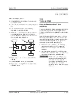
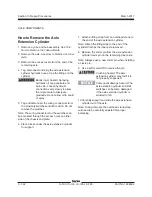
How to Remove the Axle
Extension Cylinder
1 Remove a yoke and hub assembly. See 13-2,
How to Remove the Yoke and Hub.
2 Remove the axle. See
How to Remove an Inner
Axle.
3 Remove the access covers from the end of the
remaining axle.
4 Tag, disconnect and plug the axle extension
cylinder hydraulic hoses. Cap the fittings on the
cylinder.
Bodily injury hazard. Spraying
hydraulic oil can penetrate and
burn skin. Loosen hydraulic
connections very slowly to allow
the oil pressure to dissipate
gradually. Do not allow oil to squirt
or spray.
5 Tag and disconnect the wiring connectors from
the proximity switches and limit switch. Do not
remove the switches.
Note: The wiring connectors for the switches can
be accessed through the access holes on either
side of the chassis end plate.
6 Place blocks under the axle extension cylinder
for support.
7 Attach a lifting strap from an overhead crane to
the end of the axle extension cylinder.
Note: Attach the lifting strap to the end of the
cylinder that has the inner axle removed.
8 Remove the cotter pin from the axle extension
cylinder clevis pin on the remaining inner axle.
Note: Alwayse use a new cotter pin when installing
a clevis pin.
9 Use a soft metal drift to remove the pin.
Crushing hazard. The axle
extension cylinder may fall if it is
not properly supported.
Component damage hazard. The
axle extension cylinder and limit
switches can become damaged
if the axle extension cylinder is
allowed to fall.
10 Carefully support and slide the axle extension
cylinder out of the axle.
Note: During removal, the overhead crane strap
will need to be carefully adjusted for proper
balancing.
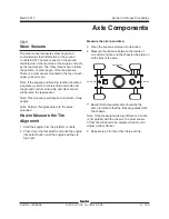
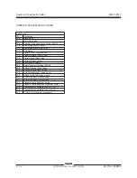
AXLE COMPONENTS
Summary of Contents for S-100
Page 246: ...March 2017 Section 6 Schematics 6 22 Safety Circuit Schematic 6 21 ...
Page 259: ...Section 6 Schematics March 2017 6 35 6 36 Electrical Schematic Generator Options ...
Page 262: ...March 2017 Section 6 Schematics 6 38 6 37 Electrical Schematic 12 kW Generator welder option ...
Page 264: ...March 2017 Section 6 Schematics 6 40 Perkins 1104D 44T Engine Electrical Schematic 6 39 ...
Page 265: ...Section 6 Schematics March 2017 6 41 Perkins 854F 34T Engine Electrical Schematic 6 42 ...
Page 268: ...March 2017 Section 6 Schematics 6 44 Perkins 854F 34T Engine Harness 6 45 ...
Page 269: ...Section 6 Schematics March 2017 6 45 Deutz TD2011L04i Engine Electrical Schematic 6 46 ...
Page 271: ...Section 6 Schematics March 2017 6 47 Deutz TD2 9 Engine Electrical Schematic 6 48 ...
Page 274: ...March 2017 Section 6 Schematics 6 50 Deutz TD2 9 Engine Electrical Harness 6 51 ...
Page 276: ...March 2017 Section 6 Schematics 6 52 6 53 Hydraulic Schematic 12 kW Generator welder option ...