


3 - 2
S-100 • S-105 • S-120 • S-125
Part No. 1268494
March 2017
Section 3 • Repair Procedures
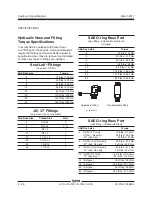
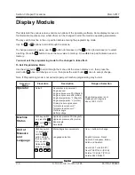
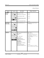
Display Module
This table lists the various screens and menu options of the operating software. Some display menus are
for informational purpose only, while others can be changed to alter the machine operating parameters.
The key switch must be in the
off
position before entering the programming mode.
Use the or
buttons to scroll through the screens.
To change parameter values, use the button (to increase) or the
button (to decrease) or to select
a setting. Press the
button to save the new value to memory. An audible beep will indicate a save to
memory.
You must exit the programming mode for the changes to take effect.
To Exit Programming Mode:
Use the scroll button to scroll through the menu until the screen displays
exit
,
then press the
plus button once, and change
no
to
yes
, then press the enter button
once to accept change.
Note: If Programming mode is not exited properly, all machine programming may be lost.
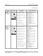
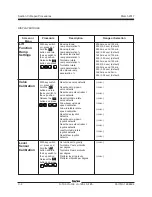
Screen or
Menu
Procedure
Description
Range or Selection
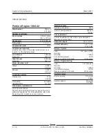
Hour meter (on power up)
Engine speed
Engine oil pressure PSI (English)
Engine oil pressure kPa (metric)
Engine temperature °F (English)
Engine temperature °C (metric)
Primary boom angle sensor
Turntable level sensor X°
Turntable level sensor Y°
Platform angle
Battery voltage
Operator
Machine
Status
Unit of
Measure
and
Language
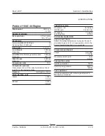
Engine temperature is not
displayed until engine is
above 100°F / 38°C
Default
With key switch
on
, press the
and at
the
same time.
Hydraulic pressure PSI (English)
Hydraulic pressure kPa (metric)
Boom angle
Axle status
Metric/English measurements
Language selection
Use +/- buttons to change
English, German, French,
Spanish, Portuguese, Italian,
Dutch and Swedish.
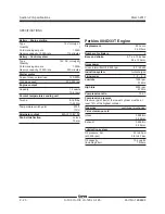
Deutz 2.9L Turbo (D2.9T)
Deutz TD2011L0.4i (DL04i)
Perkins 1104D-44T (P1104)
Perkins 854F (P854T)
With key switch
off
, press and
hold the
button and turn
the key switch to
the
on
position.
Release the
button and press
Summary of Contents for S-100
Page 246: ...March 2017 Section 6 Schematics 6 22 Safety Circuit Schematic 6 21 ...
Page 259: ...Section 6 Schematics March 2017 6 35 6 36 Electrical Schematic Generator Options ...
Page 262: ...March 2017 Section 6 Schematics 6 38 6 37 Electrical Schematic 12 kW Generator welder option ...
Page 264: ...March 2017 Section 6 Schematics 6 40 Perkins 1104D 44T Engine Electrical Schematic 6 39 ...
Page 265: ...Section 6 Schematics March 2017 6 41 Perkins 854F 34T Engine Electrical Schematic 6 42 ...
Page 268: ...March 2017 Section 6 Schematics 6 44 Perkins 854F 34T Engine Harness 6 45 ...
Page 269: ...Section 6 Schematics March 2017 6 45 Deutz TD2011L04i Engine Electrical Schematic 6 46 ...
Page 271: ...Section 6 Schematics March 2017 6 47 Deutz TD2 9 Engine Electrical Schematic 6 48 ...
Page 274: ...March 2017 Section 6 Schematics 6 50 Deutz TD2 9 Engine Electrical Harness 6 51 ...
Page 276: ...March 2017 Section 6 Schematics 6 52 6 53 Hydraulic Schematic 12 kW Generator welder option ...