


Part No. 1268494
S-100 • S-105 • S-120 • S-125
3 - 127
March 2017
Section 3 • Repair Procedures
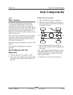
FUEL AND HYDRAULIC TANKS
11-2
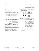
Hydraulic Tank
The primary functions of the hydraulic tank are to
cool, clean and deaerate the hydraulic fluid during
operation. It utilizes internal suction strainers for
the pump supply lines and has an external return
line filter with a filter condition indicator.
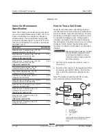
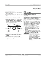
How to Remove the
Hydraulic Tank
Component damage hazard. The
work area and surfaces where
this procedure will be performed
must be clean and free of debris
that could get into the hydraulic
system.
Note: When removing a hose assembly or fitting,
the O-ring on the fitting and/or hose end must be
replaced and then torqued to specification during
installation.
Refer to Specifications,
Hydraulic Hose and Fitting
Torque Specifications.
1 Remove the ground controls side turntable
cover. See 5-1,
How to Remove a Hinged
Turntable Cover.
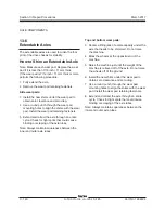
2 Close the two hydraulic shutoff valves located
at the hydraulic tank.
Component damage hazard. Be
sure that the hydraulic tank shutoff
valves are in the
open
position
before priming the pump. The
engine must not be started with
the hydraulic tank shutoff valves in
the
closed
position or component
damage will occur. If the hydraulic
tank shutoff valves are closed,
remove the key from the key
switch and tag the machine to
inform personnel of the condition.
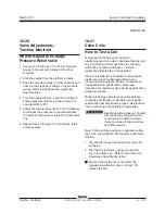
3 Remove the drain plug from the hydraulic
tank and allow all of the oil from the tank to
drain into a suitable container. See capacity
specifications.
open closed
Summary of Contents for S-100
Page 246: ...March 2017 Section 6 Schematics 6 22 Safety Circuit Schematic 6 21 ...
Page 259: ...Section 6 Schematics March 2017 6 35 6 36 Electrical Schematic Generator Options ...
Page 262: ...March 2017 Section 6 Schematics 6 38 6 37 Electrical Schematic 12 kW Generator welder option ...
Page 264: ...March 2017 Section 6 Schematics 6 40 Perkins 1104D 44T Engine Electrical Schematic 6 39 ...
Page 265: ...Section 6 Schematics March 2017 6 41 Perkins 854F 34T Engine Electrical Schematic 6 42 ...
Page 268: ...March 2017 Section 6 Schematics 6 44 Perkins 854F 34T Engine Harness 6 45 ...
Page 269: ...Section 6 Schematics March 2017 6 45 Deutz TD2011L04i Engine Electrical Schematic 6 46 ...
Page 271: ...Section 6 Schematics March 2017 6 47 Deutz TD2 9 Engine Electrical Schematic 6 48 ...
Page 274: ...March 2017 Section 6 Schematics 6 50 Deutz TD2 9 Engine Electrical Harness 6 51 ...
Page 276: ...March 2017 Section 6 Schematics 6 52 6 53 Hydraulic Schematic 12 kW Generator welder option ...


