


March 2017
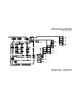
Section 5 • Schematics
5 - 6
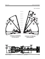
S-100 • S-105 • S-120 • S-125
Part No. 1268494
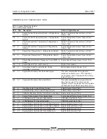
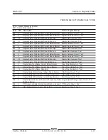
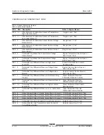
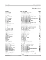
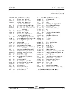
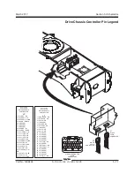
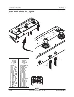
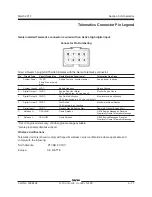
Color, Circuit #, and Primary function
OR/BK 64
Power for operational switches
BL/WH 65
Low fuel indication
BL
66
Drive enable
BL
67
Secondary boom not stowed
RD
68
Primary boom lowered
(operational)
BL
69
Primary boom #1 extended
BL/WH 70
Primary boom #2 retracted
BL/BK 71
Primary boom #2 extended
GN
72
Secondary boom extend
GN/BK 73
Secondary boom retract
RD
74
Primary #1 Lockout
RD/WH 75
Primary #2 Lockout
BL
76
Pri boom #3 extended
WH
77
Lower angle #1 operational
WH/BK 78
Upper angle #2 operational
BK
79
power from TCON ESTOP
N/A
80
Can 2.0/J1939 Shield
GN
81
Can 2.0/J1939 Low
YL
82
Can 2.0/J1939 High
GN/WH 83
Tilt signal x axis
GN/BK 84
Tilt signal y axis
GN
85
Tilt sensor power
OR
86
Hydraulic filter restricted
RD
87
Platform level safety power
RD/BK 88
Platform level safety output
BR
89
Platform level safety ground
RD/BK 90
Proximity kill
RD/WH 91
Gate Interlock
WH/BK 92
Motor speed (LO/HI)
WH/RD 93
Motor bypass
WH
94
Load sensor
OR
95
Tether ESTOP return
RD
96
Tether power
BK
97
Tether ESTOP power
WH
98
J1708 + (high)
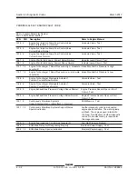
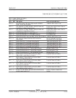
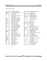
Color, Circuit #, and Primary function
BK
99
J1708 - (low)
WH/RD 100 Outrigger lowered
WH/BK 101 Outrigger raised
OR
102 Pothole protector up
OR/RD 103 Pothole protector down
BK/WH 104 Proprietary data buss –
(i.e. ITT or AP)
BK/RD 105 Proprietary data buss +
(i.e. ITT or AP)
GN 106 Spare
RD
107 Alternator field
BL/WH 108 Engine status
GN/WH 109 Sensor pwr
BK
110 Sensor return
OR
111 Steer signal
RD
112 Steer signal to solenoid valve
OR/RD 113 Multi function valve
BK/RD 114 Load moment overweight
RD/BK 115 Load moment underweight
OR
116 Hydraulic oil cooler
RD
117 Flashing beacon
OR
118 Lift speed reduction
BL
119 Hydraulic pressure sensor output
OR
120 Oil cooler fan
GR
121 Axle oscillate LEFT
GN/BK 122 Axle oscillate RIGHT
RD/BK 123 Primary boom angle signal
operational
RD/WH 124 Secondary boom angle signal
operational
WH/RD 125 Secondary boomlockout
(Ext Enable)
WH/BK 126 Secondary boom lockout
(Riser Down Enable)
GN
127 ECU test switch
OR/RD 128 Low engine speed
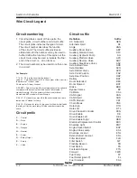
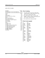
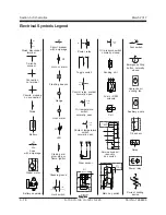
WIRE CIRCUIT LEGEND
Summary of Contents for S-100
Page 246: ...March 2017 Section 6 Schematics 6 22 Safety Circuit Schematic 6 21 ...
Page 259: ...Section 6 Schematics March 2017 6 35 6 36 Electrical Schematic Generator Options ...
Page 262: ...March 2017 Section 6 Schematics 6 38 6 37 Electrical Schematic 12 kW Generator welder option ...
Page 264: ...March 2017 Section 6 Schematics 6 40 Perkins 1104D 44T Engine Electrical Schematic 6 39 ...
Page 265: ...Section 6 Schematics March 2017 6 41 Perkins 854F 34T Engine Electrical Schematic 6 42 ...
Page 268: ...March 2017 Section 6 Schematics 6 44 Perkins 854F 34T Engine Harness 6 45 ...
Page 269: ...Section 6 Schematics March 2017 6 45 Deutz TD2011L04i Engine Electrical Schematic 6 46 ...
Page 271: ...Section 6 Schematics March 2017 6 47 Deutz TD2 9 Engine Electrical Schematic 6 48 ...
Page 274: ...March 2017 Section 6 Schematics 6 50 Deutz TD2 9 Engine Electrical Harness 6 51 ...
Page 276: ...March 2017 Section 6 Schematics 6 52 6 53 Hydraulic Schematic 12 kW Generator welder option ...


