

4 - 30
S-100 • S-105 • S-120 • S-125
Part No. 1268494
March 2017
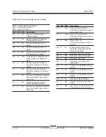
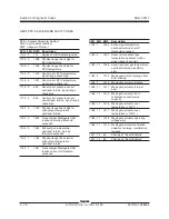
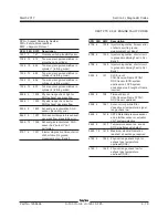
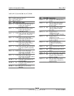
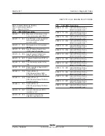
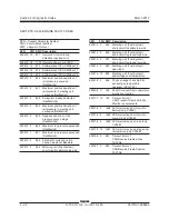
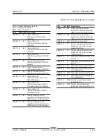
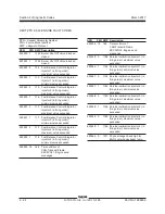
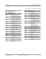
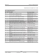
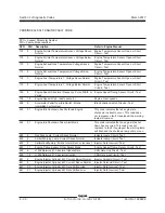
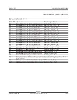
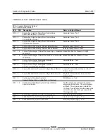
Section 4 • Diagnostic Codes
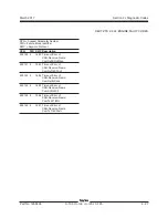
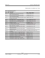
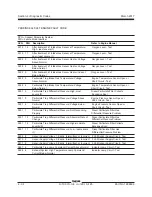
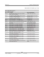
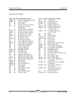
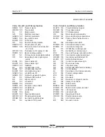
SPN = Suspect Parameter Number
FMI = Failure Mode Identifier
SPN FMI Description Refer to Engine Manual
172 3 Engine Air Inlet Temperature Sensor: Voltage Above Engine Temperature Sensor Open or Short
Normal Circuit - Test
172 3 Engine Air Inlet Temperature Sensor: Voltage Below Engine Temperature Sensor Open or Short
Normal Circuit - Test
173 3 Engine Exhaust Gas Temperature: Voltage Above Engine Temperature Sensor Open or Short
Normal Circuit - Test
173 4 Engine Exhaust Gas Temperature: Voltage Below Engine Temperature Sensor Open or Short
Normal Circuit - Test
174 3 Engine Fuel Temperature 1: Voltage Above Normal Engine Temperature Sensor Open or Short
Circuit - Test
174 4 Engine Fuel Temperature 1: Voltage Below Normal Engine Temperature Sensor Open or Short
Circuit - Test
190 8 Engine Speed: Abnormal Frequency, Pulse Width, or Engine Speed/Timing Sensor Circuit - Test
Period
190 15 Engine Speed: High - least severe (1) Engine Over speeds
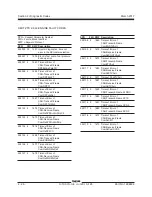
558 2 Accelerator Pedal1Low Idle Switch: Erratic, Idle Validation Switch Circuits - Test
Intermittent, or Incorrect
593 31 Engine Idle Shutdown has Shutdown Engine This code indicates that an engine idle
shutdown is about to occur. This code does
not represent a fault. If equipped, the warning
lamp will come on.
594 31 Engine Idle Shutdown Driver Alert Mode This code indicates that an engine idle shut
down has occurred. This code does not
represent a fault. If equipped, the warning lamp
will flash and the shutdown lamp will come on.
623 6 Red Stop Lamp: Current Above Normal Indicator Lamp Circuit- Test
624 6 Amber Warning Lamp: Current Above Normal Indicator Lamp Circuit- Test
630 2 Calibration Memory: Erratic, Intermittent, or Incorrect Injector Data Incorrect- Test
637 11 Engine Timing Sensor: Other Failure Mode Engine Speed/Timing Sensor Circuit - Test
639 9 J1939 Network #1: Abnormal Update Rate CAN Data Link Circuit - Test
639 14 J1939 Network #1: Special Instruction CAN Data Link Circuit - Test
651 5 Engine Injector Cylinder #01: Current Below Normal Injector Solenoid Circuit - Test
651 6 Engine Injector Cylinder #01: Current Above Normal Injector Solenoid Circuit - Test
651 20 Engine Injector Cylinder #01: Data Drifted High Injector Data Incorrect- Test
651 21 Engine Injector Cylinder #01: Data Drifted Low Injector Data Incorrect- Test
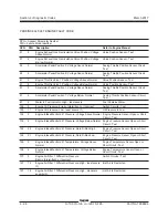
PERKINS 854F-34T ENGINE FAULT CODE
Summary of Contents for S-100
Page 246: ...March 2017 Section 6 Schematics 6 22 Safety Circuit Schematic 6 21 ...
Page 259: ...Section 6 Schematics March 2017 6 35 6 36 Electrical Schematic Generator Options ...
Page 262: ...March 2017 Section 6 Schematics 6 38 6 37 Electrical Schematic 12 kW Generator welder option ...
Page 264: ...March 2017 Section 6 Schematics 6 40 Perkins 1104D 44T Engine Electrical Schematic 6 39 ...
Page 265: ...Section 6 Schematics March 2017 6 41 Perkins 854F 34T Engine Electrical Schematic 6 42 ...
Page 268: ...March 2017 Section 6 Schematics 6 44 Perkins 854F 34T Engine Harness 6 45 ...
Page 269: ...Section 6 Schematics March 2017 6 45 Deutz TD2011L04i Engine Electrical Schematic 6 46 ...
Page 271: ...Section 6 Schematics March 2017 6 47 Deutz TD2 9 Engine Electrical Schematic 6 48 ...
Page 274: ...March 2017 Section 6 Schematics 6 50 Deutz TD2 9 Engine Electrical Harness 6 51 ...
Page 276: ...March 2017 Section 6 Schematics 6 52 6 53 Hydraulic Schematic 12 kW Generator welder option ...


