


3 - 28
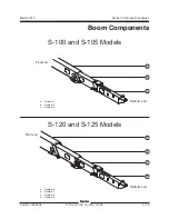
S-100 • S-105 • S-120 • S-125
Part No. 1268494
March 2017
Section 3 • Repair Procedures
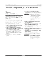
JIB BOOM COMPONENTS, S-105 AND S-125 MODELS
3-2
Jib Boom Lift Cylinder,
S-105 and S-125 Models
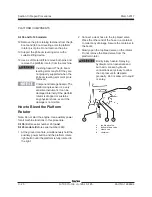
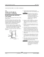
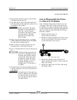
How to Remove the Jib Boom
Lift Cylinder
Note: Perform this procedure with the boom in the
stowed position.
Note: When removing a hose assembly or fitting,
the O-ring on the fitting and/or hose end must be
replaced and then torqued to specification during
installation. Refer to Specifications,
Hydraulic
Hose and Fitting Torque Specifications.
1 Raise the jib boom slightly and place blocks
under the platform mounting weldment. Lower
the jib boom until the platform is resting on the
blocks just enough to support the platform.
Note: Do not rest the entire weight of the boom on
the blocks.
2 Tag, disconnect and plug the jib boom lift
cylinder hydraulic hoses. Cap the fittings on the
cylinder.
Bodily injury hazard. Spraying
hydraulic oil can penetrate and
burn skin. Loosen hydraulic
connections very slowly to allow
the oil pressure to dissipate
gradually. Do not allow oil to
squirt or spray.
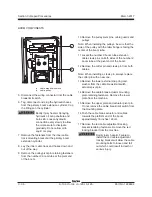
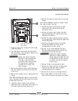
3 Remove the hose and cable cover retaining
fasteners from the jib boom leveling arm.
Remove the hose and cable cover from the
machine.
4 Remove the pin retaining fasteners from the
jib boom lift cylinder rod-end pivot pin. Do not
remove the pin.
5 Use a soft metal drift to tap the jib boom lift
cylinder rod-end pivot pin half way out and
lower one of the leveling arms to the ground.
Tap the pin the other direction and lower the
opposite leveling arm. Do not remove the pin.
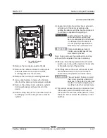
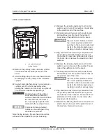
6 Support the jib boom lift cylinder with a suitable
lifting device.
7 Remove the pin retaining fastener from the jib
boom lift cylinder barrel-end pivot pin. Use a
soft metal drift to remove the barrel-end pivot
pin.
8 Use a soft metal drift to remove the jib boom
lift cylinder rod-end pivot pin. Remove the jib
boom lift cylinder from the machine.
Crushing hazard. The jib boom lift
cylinder may become unbalanced
and fall when it is removed from
the machine if it is not properly
supported.
Summary of Contents for S-100
Page 246: ...March 2017 Section 6 Schematics 6 22 Safety Circuit Schematic 6 21 ...
Page 259: ...Section 6 Schematics March 2017 6 35 6 36 Electrical Schematic Generator Options ...
Page 262: ...March 2017 Section 6 Schematics 6 38 6 37 Electrical Schematic 12 kW Generator welder option ...
Page 264: ...March 2017 Section 6 Schematics 6 40 Perkins 1104D 44T Engine Electrical Schematic 6 39 ...
Page 265: ...Section 6 Schematics March 2017 6 41 Perkins 854F 34T Engine Electrical Schematic 6 42 ...
Page 268: ...March 2017 Section 6 Schematics 6 44 Perkins 854F 34T Engine Harness 6 45 ...
Page 269: ...Section 6 Schematics March 2017 6 45 Deutz TD2011L04i Engine Electrical Schematic 6 46 ...
Page 271: ...Section 6 Schematics March 2017 6 47 Deutz TD2 9 Engine Electrical Schematic 6 48 ...
Page 274: ...March 2017 Section 6 Schematics 6 50 Deutz TD2 9 Engine Electrical Harness 6 51 ...
Page 276: ...March 2017 Section 6 Schematics 6 52 6 53 Hydraulic Schematic 12 kW Generator welder option ...


