

Part No. 1268494
S-100 • S-105 • S-120 • S-125
3 - 21
March 2017
Section 3 • Repair Procedures
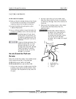
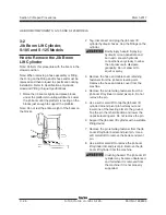
4 Hold the platform rotate left button until the
platform is fully rotated. Continue holding the
button until air stops coming out of the bleed
valve. Close the bleed valve.
Crushing hazard. Keep clear of
the platform during rotation.
5 Connect the clear hose to the bottom bleed
valve and slowly open the valve. Do not remove
the bleed valve.
6 Hold the platform rotate right button until the
platform is fully rotated. Continue holding the
button until air stops coming out of the bleed
valve. Close the bleed valve.
Crushing hazard. Keep clear of
the platform during rotation.
7 Remove the hose from the bleed valve and
clean up any hydraulic oil that may have spilled.
8 Rotate the platform full right then left and
inspect the bleed valves for leaks.
9 Clean up any oil that may have spilled during
this procedure.
S-100, S-120, S-105
(after serial number 250)
and
S-125 models
(after serial number 998)
:
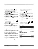
1. Rotate the platform full right, then full left until
air is completely out of the rotator. Bleeding the
valve is not necessary.
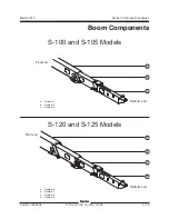
PLATFORM COMPONENTS
2-4
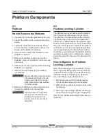
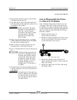
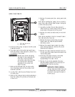
Platform Level Sensor
The platform level sensor is mounted to the side
of the platform rotator. The platform level sensor
is monitored by the control system to maintain a
level platform throughout boom range of motion.
If a platform level sensor is replaced, it must be
calibrated prior to machine operation.
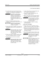
How to Calibrate the
Platform Level Sensor
Note: Perform this procedure with the machine on
a firm, level surface and in the stowed position.
1 Secure a digital level to one of the side railings
of the platform.
2 Start the machine and level the platform to
gravity. Push the red Emergency stop button in
to stop the engine.
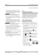
3 Press and hold the enter button
on the
ground control panel while pulling out the red
Emergency Stop button.
4 Press the plus button
, then press the enter
button
twice before again pressing the plus
button
.
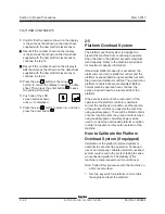
5 Press the enter button
three timees until
p
latform
l
evel
to
g
ravity
is displayed on the
LCD screen.
6 Press the plus button
once.
7 Press the enter button
to save the setting in
memory.
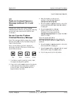
8 Push one of the LCD
screen buttons shown
until
platform
level
sensor
mv
per
degree
is displayed.
Summary of Contents for S-100
Page 246: ...March 2017 Section 6 Schematics 6 22 Safety Circuit Schematic 6 21 ...
Page 259: ...Section 6 Schematics March 2017 6 35 6 36 Electrical Schematic Generator Options ...
Page 262: ...March 2017 Section 6 Schematics 6 38 6 37 Electrical Schematic 12 kW Generator welder option ...
Page 264: ...March 2017 Section 6 Schematics 6 40 Perkins 1104D 44T Engine Electrical Schematic 6 39 ...
Page 265: ...Section 6 Schematics March 2017 6 41 Perkins 854F 34T Engine Electrical Schematic 6 42 ...
Page 268: ...March 2017 Section 6 Schematics 6 44 Perkins 854F 34T Engine Harness 6 45 ...
Page 269: ...Section 6 Schematics March 2017 6 45 Deutz TD2011L04i Engine Electrical Schematic 6 46 ...
Page 271: ...Section 6 Schematics March 2017 6 47 Deutz TD2 9 Engine Electrical Schematic 6 48 ...
Page 274: ...March 2017 Section 6 Schematics 6 50 Deutz TD2 9 Engine Electrical Harness 6 51 ...
Page 276: ...March 2017 Section 6 Schematics 6 52 6 53 Hydraulic Schematic 12 kW Generator welder option ...


