


Part No. 1268494
S-100 • S-105 • S-120 • S-125
3 - 123
March 2017
Section 3 • Repair Procedures
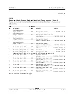
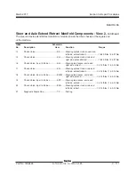
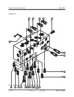
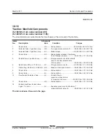
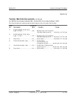
10-20
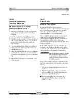
Valve Adjustments -
Traction Manifold
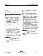
How to Adjust the Charge
Pressure Relief Valve
1 Connect a 0 to 600 psi / 0 to 41 bar pressure
gauge to the test port located on the drive
manifold.
2 Start the engine from the platform controls.
3 Drive the machine slowly in either direction and
observe the pressure reading on the pressure
gauge. Refer to Specifications,
Hydraulic
Specifications.
4 Turn the engine off. Use a wrench to hold the
charge pressure relief valve and remove the
cap (item DM or FF).
5 Adjust the internal hex socket. Turn it clockwise
to increase the pressure or counterclockwise
to decrease the pressure. Install the relief valve
cap.
6 Repeat steps 2 through 5 to confirm the relief
valve pressure.
MANIFOLDS
10-21
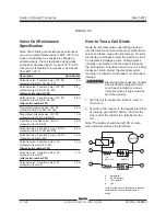
Valve Coils
How to Test a Coil
A properly functioning coil provides an
electromagnetic force which operates the solenoid
valve. Critical to normal operation is continuity
within the coil. Zero resistance or infinite
resistance indicates the coil has failed.
Since coil resistance is sensitive to temperature,
resistance values outside specification can
produce erratic operation. When coil resistance
decreases below specification, amperage
increases. As resistance rises above specification,
voltage increases.
While valves may operate when coil resistance
is outside specification, maintaining coils within
specification will help ensure proper valve function
over a wide range of operating temperatures.
Electrocution/burn hazard. Contact
with electrically charged circuits
could result in death or serious
injury. Remove all rings, watches
and other jewelry.
Note: If the machine has been in operation, allow
the coil to cool at least 3 hours before performing
this test.
1 Tag and disconnect the wiring from the coil to
be tested.
2 Test the coil resistance using a multimeter
set to resistance (
Ω)
. Refer to the Valve Coil
Resistance Specification table.
Result: If the resistance is not within the
adjusted specification, plus or minus 10%,
replace the coil.
Summary of Contents for S-100
Page 246: ...March 2017 Section 6 Schematics 6 22 Safety Circuit Schematic 6 21 ...
Page 259: ...Section 6 Schematics March 2017 6 35 6 36 Electrical Schematic Generator Options ...
Page 262: ...March 2017 Section 6 Schematics 6 38 6 37 Electrical Schematic 12 kW Generator welder option ...
Page 264: ...March 2017 Section 6 Schematics 6 40 Perkins 1104D 44T Engine Electrical Schematic 6 39 ...
Page 265: ...Section 6 Schematics March 2017 6 41 Perkins 854F 34T Engine Electrical Schematic 6 42 ...
Page 268: ...March 2017 Section 6 Schematics 6 44 Perkins 854F 34T Engine Harness 6 45 ...
Page 269: ...Section 6 Schematics March 2017 6 45 Deutz TD2011L04i Engine Electrical Schematic 6 46 ...
Page 271: ...Section 6 Schematics March 2017 6 47 Deutz TD2 9 Engine Electrical Schematic 6 48 ...
Page 274: ...March 2017 Section 6 Schematics 6 50 Deutz TD2 9 Engine Electrical Harness 6 51 ...
Page 276: ...March 2017 Section 6 Schematics 6 52 6 53 Hydraulic Schematic 12 kW Generator welder option ...


