


Part No. 1268494
S-100 • S-105 • S-120 • S-125
3 - 113
March 2017
Section 3 • Repair Procedures
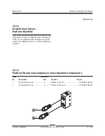
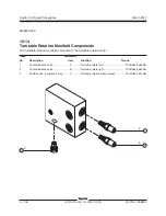
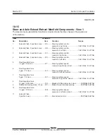
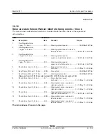
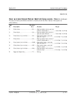
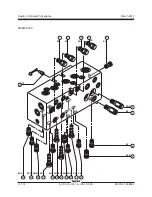
MANIFOLDS
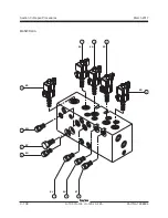
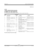
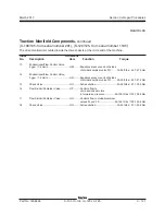
10-17
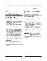
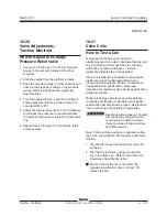
Valve Adjustments - Steer and
Axle Extend/Retract Manifold
How to Adjust the Steer and Axle
Retract Relief Valve
Note: Perform this procedure with the axles
retracted and the boom in the stowed position.
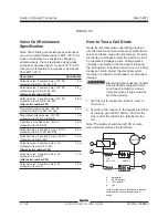
1 Connect a 0 to 5000 psi / 0 to 345 bar pressure
gauge to the test port on the steer and axle
extend/retract manifold.
2 Start the engine from the platform controls.
3 Position the machine so that the left front wheel
is against an immoveable object such as a
curb.
4 Press down the foot switch and activate the
steer function. Steer the wheel into the curb
and hold. Observe the pressure reading on
the pressure gauge. Refer to Specifications,
Hydraulic Component Specifications.
5 Turn the engine off. Use a wrench to hold the
relief valve and remove the cap (item EZ).
6 Adjust the internal hex socket. Turn it clockwise
to increase the pressure or counterclockwise to
decrease the pressure. Install the relief valve
cap.
Tip-over hazard. Do not adjust
the relief valve higher than
specified.
7 Repeat steps 2 through 6 to confirm relief valve
pressure.
How to Adjust the Axle Extend
Relief Valve
Note: Perform this procedure with the axles
retracted, the boom in the stowed position and the
machine on a paved surface.
1 Connect a 0 to 5000 psi / 0 to 345 bar pressure
gauge to the test port on the steer and axle
extend/retract manifold.
2 Start the engine from the platform controls.
3 Press down the foot switch and push the axle
extend button. Observe the pressure reading
on the pressure gauge. Refer to Specifications,
Hydraulic Specifications.
4 Turn the engine off. Use a wrench to hold the
relief valve and remove the cap (item EQQ).
5 Adjust the internal hex socket. Turn it clockwise
to increase the pressure or counterclockwise to
decrease the pressure. Install the relief valve
cap.
Tip-over hazard. Do not adjust
the relief valve higher than
specified.
6 Repeat steps 2 through 5 to confirm relief valve
pressure.
Summary of Contents for S-100
Page 246: ...March 2017 Section 6 Schematics 6 22 Safety Circuit Schematic 6 21 ...
Page 259: ...Section 6 Schematics March 2017 6 35 6 36 Electrical Schematic Generator Options ...
Page 262: ...March 2017 Section 6 Schematics 6 38 6 37 Electrical Schematic 12 kW Generator welder option ...
Page 264: ...March 2017 Section 6 Schematics 6 40 Perkins 1104D 44T Engine Electrical Schematic 6 39 ...
Page 265: ...Section 6 Schematics March 2017 6 41 Perkins 854F 34T Engine Electrical Schematic 6 42 ...
Page 268: ...March 2017 Section 6 Schematics 6 44 Perkins 854F 34T Engine Harness 6 45 ...
Page 269: ...Section 6 Schematics March 2017 6 45 Deutz TD2011L04i Engine Electrical Schematic 6 46 ...
Page 271: ...Section 6 Schematics March 2017 6 47 Deutz TD2 9 Engine Electrical Schematic 6 48 ...
Page 274: ...March 2017 Section 6 Schematics 6 50 Deutz TD2 9 Engine Electrical Harness 6 51 ...
Page 276: ...March 2017 Section 6 Schematics 6 52 6 53 Hydraulic Schematic 12 kW Generator welder option ...


