


3 - 50
S-100 • S-105 • S-120 • S-125
Part No. 1268494
March 2017
Section 3 • Repair Procedures
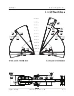
BOOM COMPONENTS
b
c
d
a
4-5
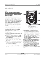
Boom Extend/Retract Cables
How to Adjust the Boom Extend/
Retract Cables
Properly adjusted extend/retract cables are
essential to safe machine operation. Failure to
maintain proper adjustment of the cables could
result in unsafe operating conditions and may
cause component damage. The boom extend and
retract functions should operate smoothly and be
free of hesitation, jerking and unusual noise.
Note: A flashlight may be necessary to be able to
see the extend/retract cables inside of the boom
assembly.
Note: Perform this procedure with the boom fully
retracted.
1 Start the engine from the ground controls.
2 Raise the boom to a horizontal position.
3 Stop the engine.
4 Remove the boom end cover from the pivot end
of the machine.
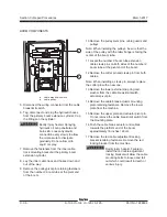
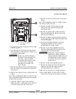
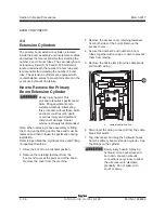
5 Locate the red locking bracket (c) covering the
cable adjustment bolts at the pivot end of the
boom (illustration 1).
6 Remove the retaining fastener from the red
locking bracket and remove the bracket from
the machine.
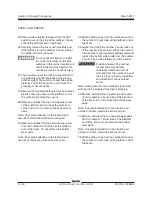
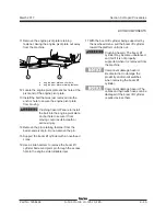
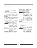
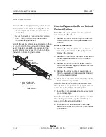
7 Locate the retract cable equalizer bolt under the
number 1 boom tube at the platform end of the
boom assembly (illustration 3).
8 Loosen the nylock (g) and jam nut (h) on the
cable tension equalizer bracket. Do not remove
the nuts.
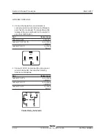
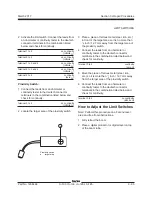
a
limit switch
b
extend cable adjustment bolts
c
red cable adjustment locking bracket
d
boom tube distance
Illustration 1
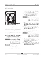
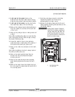
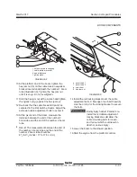
9 At the pivot end of the boom (illustration 1),
turn the cable adjustment bolts (b) clockwise
to obtain 6
3
/
4
inches / 17 cm between the end
of the number 3 boom tube and the end of the
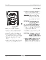
number 2 boom tube (d). As a guide (Illustration
2), the end of the extension cable coupling (i)
should be approximately mid-point (k) between
the guide plate (l) and the cable retainer
bracket (j). Illustration 2 is visible by removing
the boom side covers.
Note: Adjust the cable adjustment bolts evenly so
the cable break limit switch (a) stays centered in
the limit switch actuator (Illustration 1).
Note: If the distance is greater than 6
3
/
4
inches /
17 cm, loosen the extend cable adjustment bolts
and tighten the hex jam nut on the cable tension
equalizer bolt until the distance is less than
6
3
/
4
inches / 17 cm. Loosen the jam nut and repeat
step 9.
Summary of Contents for S-100
Page 246: ...March 2017 Section 6 Schematics 6 22 Safety Circuit Schematic 6 21 ...
Page 259: ...Section 6 Schematics March 2017 6 35 6 36 Electrical Schematic Generator Options ...
Page 262: ...March 2017 Section 6 Schematics 6 38 6 37 Electrical Schematic 12 kW Generator welder option ...
Page 264: ...March 2017 Section 6 Schematics 6 40 Perkins 1104D 44T Engine Electrical Schematic 6 39 ...
Page 265: ...Section 6 Schematics March 2017 6 41 Perkins 854F 34T Engine Electrical Schematic 6 42 ...
Page 268: ...March 2017 Section 6 Schematics 6 44 Perkins 854F 34T Engine Harness 6 45 ...
Page 269: ...Section 6 Schematics March 2017 6 45 Deutz TD2011L04i Engine Electrical Schematic 6 46 ...
Page 271: ...Section 6 Schematics March 2017 6 47 Deutz TD2 9 Engine Electrical Schematic 6 48 ...
Page 274: ...March 2017 Section 6 Schematics 6 50 Deutz TD2 9 Engine Electrical Harness 6 51 ...
Page 276: ...March 2017 Section 6 Schematics 6 52 6 53 Hydraulic Schematic 12 kW Generator welder option ...


