


Part No. 1268494
S-100 • S-105 • S-120 • S-125
3 - 81
March 2017
Section 3 • Repair Procedures
10-2
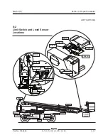
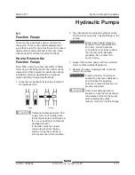
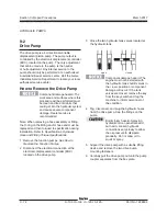
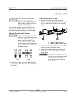
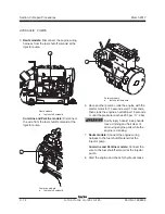
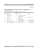
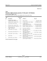
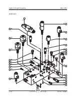
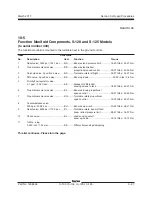
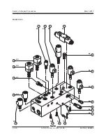
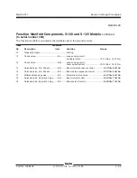
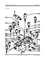
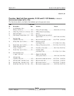
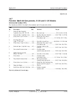
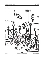
Function Manifold Components, S-100 and S-105 Models
(from serial number 137)
The function manifold is mounted to the turntable next to the ground controls.
Index
Schematic
No.
Description
Item
Function
Torque
1
Solenoid Valve Assembly,
3 position 4 way, DO3, 12V DC
......... FD ..........Boom up/down .............................................
30-35 in-lbs / 3-4 Nm
2
Solenoid Valve, 3 position 4 way
.......
FC
..........Turntable rotate control, left/right ..............
25-27 ft-lbs / 34-37 Nm
3
Proportional Solenoid Valve
............... FG ..........Turntable rotate,
proportional speed control .................
18-20 ft-lbs / 25-27 Nm
4
Solenoid Valve, 2 position 3 way
....... AA ..........
Auxiliary drive/steer selector
.....................
25-27 ft-lbs / 34-37 Nm
5
Relief Valve, 3000 psi / 206.8 bar
......
AC
..........Platform manifold pressure limit ...............18-20 ft-lbs / 24-27 Nm
6
Flow Regulator Valve,
3 gpm / 11.36 L/min
........................... AD ..........Priority flow to platform .............................
25-27 ft-lbs / 34-37 Nm
7
Check Valve, 5 psi / 0.34 bar
............. AE ..........
Blocks flow from pump 2
to auxiliary pump
............................
12-14 ft-lbs / 16.3-19 Nm
8
Proportional Solenoid Valve, N.C.
...... FF ..........Primary lift, proportional
valve speed control .............................
33-37 ft-lbs / 45-50 Nm
9
Check Valve, 10 psi / 0.69 bar
........... AB ..........
Blocks flow from pump 1 and 2
to auxiliary pump
.........................
18-20 ft-lbs / 24.5-27.2 Nm
10
Check Valve
....................................... AG ..........
Blocks flow from auxiliary pump,
port 2A to pump 1 ..............................
33-37 ft-lbs / 45-50 Nm
11
Check Valve, 5 psi / 0.34 bar
............. AF ..........
Blocks flow from auxiliary pump,
ports 2A and 3A to pump 2
................
25-27 ft-lbs / 34-37 Nm
This list continues on the next page.
MANIFOLDS
Summary of Contents for S-100
Page 246: ...March 2017 Section 6 Schematics 6 22 Safety Circuit Schematic 6 21 ...
Page 259: ...Section 6 Schematics March 2017 6 35 6 36 Electrical Schematic Generator Options ...
Page 262: ...March 2017 Section 6 Schematics 6 38 6 37 Electrical Schematic 12 kW Generator welder option ...
Page 264: ...March 2017 Section 6 Schematics 6 40 Perkins 1104D 44T Engine Electrical Schematic 6 39 ...
Page 265: ...Section 6 Schematics March 2017 6 41 Perkins 854F 34T Engine Electrical Schematic 6 42 ...
Page 268: ...March 2017 Section 6 Schematics 6 44 Perkins 854F 34T Engine Harness 6 45 ...
Page 269: ...Section 6 Schematics March 2017 6 45 Deutz TD2011L04i Engine Electrical Schematic 6 46 ...
Page 271: ...Section 6 Schematics March 2017 6 47 Deutz TD2 9 Engine Electrical Schematic 6 48 ...
Page 274: ...March 2017 Section 6 Schematics 6 50 Deutz TD2 9 Engine Electrical Harness 6 51 ...
Page 276: ...March 2017 Section 6 Schematics 6 52 6 53 Hydraulic Schematic 12 kW Generator welder option ...


