


Part No. 1268494
S-100 • S-105 • S-120 • S-125
3 - 7
March 2017
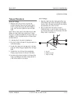
Section 3 • Repair Procedures
7 Locate the ECM circuit board mounted to the
inside of the platform control box.
Electrocution/burn hazard. Contact
with electrically charged circuits
could result in death or serious
injury. Remove all rings, watches
and other jewelry.
Component damage hazard.
Electrostatic discharge (ESD)
can damage printed circuit board
components. Maintain firm contact
with a metal part of the machine
that is grounded at all times when
handling printed circuit boards OR
use a grounded wrist strap.
8 Remove the ECM circuit board mounting
fasteners.
9 Carefully remove the ECM circuit board from
the platform control box.
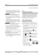
How to Remove the Membrane
Circuit Board
1 Push in the Emergency Stop button to the
off
position at both the ground and platform
controls.
2 Remove the platform control box lid retaining
fasteners. Open the control box lid.
1-1
Circuit Boards
Note: When an ECM circuit board is replaced, the
joystick controllers will need to be calibrated. See
1-3,
How to Calibrate a Joystick Controller.
How to Remove the ECM
Circuit Board
1 Push in the Emergency Stop button to the
off
position at both the ground and platform
controls.
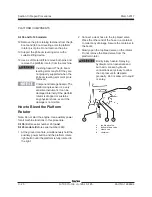
2 Remove the platform control box mounting
fasteners. Remove the platform control box
from the machine.
Component damage hazard.
Cables can be damaged if they
are kinked or pinched.
3 Locate the cables that connect to the bottom
of the control box. Number each cable and its
location at the control box.
4 Disconnect the cables from the bottom of the
platform control box.
5 Remove the control cable plug retaining
fasteners from the bottom of the platform
control box.
6 Remove the platform control box lid retaining
fasteners. Open the control box lid.
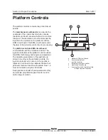
PLATFORM CONTROLS
Summary of Contents for S-100
Page 246: ...March 2017 Section 6 Schematics 6 22 Safety Circuit Schematic 6 21 ...
Page 259: ...Section 6 Schematics March 2017 6 35 6 36 Electrical Schematic Generator Options ...
Page 262: ...March 2017 Section 6 Schematics 6 38 6 37 Electrical Schematic 12 kW Generator welder option ...
Page 264: ...March 2017 Section 6 Schematics 6 40 Perkins 1104D 44T Engine Electrical Schematic 6 39 ...
Page 265: ...Section 6 Schematics March 2017 6 41 Perkins 854F 34T Engine Electrical Schematic 6 42 ...
Page 268: ...March 2017 Section 6 Schematics 6 44 Perkins 854F 34T Engine Harness 6 45 ...
Page 269: ...Section 6 Schematics March 2017 6 45 Deutz TD2011L04i Engine Electrical Schematic 6 46 ...
Page 271: ...Section 6 Schematics March 2017 6 47 Deutz TD2 9 Engine Electrical Schematic 6 48 ...
Page 274: ...March 2017 Section 6 Schematics 6 50 Deutz TD2 9 Engine Electrical Harness 6 51 ...
Page 276: ...March 2017 Section 6 Schematics 6 52 6 53 Hydraulic Schematic 12 kW Generator welder option ...


