


Part No. 1268494
S-100 • S-105 • S-120 • S-125
3 - 57
March 2017
Section 3 • Repair Procedures
ENGINES
1
2
3
4
5
6
7
8
1
2
3
4
5
6
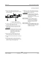
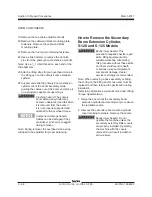
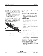
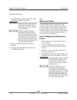
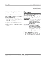
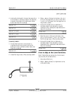
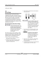
How to Install the Flex Plate
1 Install the flex plate onto the engine flywheel
with the raised spline towards the pump.
2 Apply Loctite
®
removable thread sealant to the
mounting fasteners. Then torque the flex plate
mounting bolts in sequence to:
Cummins engines
: 23 ft-lbs / 31.2 Nm.
Deutz and Perkins engines
: 28 ft-lbs / 38 Nm.
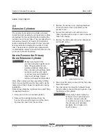
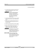
3 Install the pump coupler onto the pump shaft
with the set screw toward the pump. Leave the
appropriate gap between coupler and pump
end plate for your engine.
4 Apply Loctite
®
removable thread sealant to the
pump coupler set screw.
Perkins and Cummins engines before serial
number 1029 and Deutz 913 engines:
Torque the set screw to 20 ft-lbs / 27 Nm.
Perkins and Cummins engines after serial
number 1028 and Deutz 2011 engines:
Torque the set screw to 61 ft-lbs / 83 Nm.
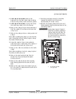
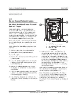
5 Install the bell housing/mounting plate
assembly. Apply Loctite
®
removable thread
sealant to the mounting fasteners. Then torque
the pump retaining fasteners to:
Cummins, Perkins and Deutz 913 engines
:
28 ft-lbs / 38 Nm.
Deutz 2011 engines
: 47 ft-lbs / 63 Nm.
Component damage hazard. Do
not force the drive pump during
installation or the flex plate teeth
may become damaged.
Component damage hazard.
When installing the pump, do not
force the pump coupler into the
flexplate or damage to the pump
shaft seal may occur.
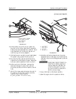
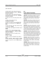
1
2
3
4
5
6
7
8
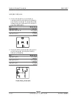
Perkins Engines
Cummins Engines
After Serial Number 1028
Deutz 2011 Engines
Perkins Engines
Cummins Engines
Before Serial Number 1029
Deutz 913 Engines
Summary of Contents for S-100
Page 246: ...March 2017 Section 6 Schematics 6 22 Safety Circuit Schematic 6 21 ...
Page 259: ...Section 6 Schematics March 2017 6 35 6 36 Electrical Schematic Generator Options ...
Page 262: ...March 2017 Section 6 Schematics 6 38 6 37 Electrical Schematic 12 kW Generator welder option ...
Page 264: ...March 2017 Section 6 Schematics 6 40 Perkins 1104D 44T Engine Electrical Schematic 6 39 ...
Page 265: ...Section 6 Schematics March 2017 6 41 Perkins 854F 34T Engine Electrical Schematic 6 42 ...
Page 268: ...March 2017 Section 6 Schematics 6 44 Perkins 854F 34T Engine Harness 6 45 ...
Page 269: ...Section 6 Schematics March 2017 6 45 Deutz TD2011L04i Engine Electrical Schematic 6 46 ...
Page 271: ...Section 6 Schematics March 2017 6 47 Deutz TD2 9 Engine Electrical Schematic 6 48 ...
Page 274: ...March 2017 Section 6 Schematics 6 50 Deutz TD2 9 Engine Electrical Harness 6 51 ...
Page 276: ...March 2017 Section 6 Schematics 6 52 6 53 Hydraulic Schematic 12 kW Generator welder option ...


